

Optical touch screen
An optical touch screen and optical reflection technology, applied in the direction of instruments, electrical digital data processing, data processing input/output process, etc., can solve the problems of reducing the touch experience, reducing the service life of the touch screen, and large damage to the touch screen, so as to improve the touch Experience, Change Sensitivity, Improve Sensitivity Effects
- Summary
- Abstract
- Description
- Claims
- Application Information
AI Technical Summary
Problems solved by technology
Method used
Image

Examples
Embodiment Construction
[0019] Below in conjunction with accompanying drawing and embodiment the present invention is further described:
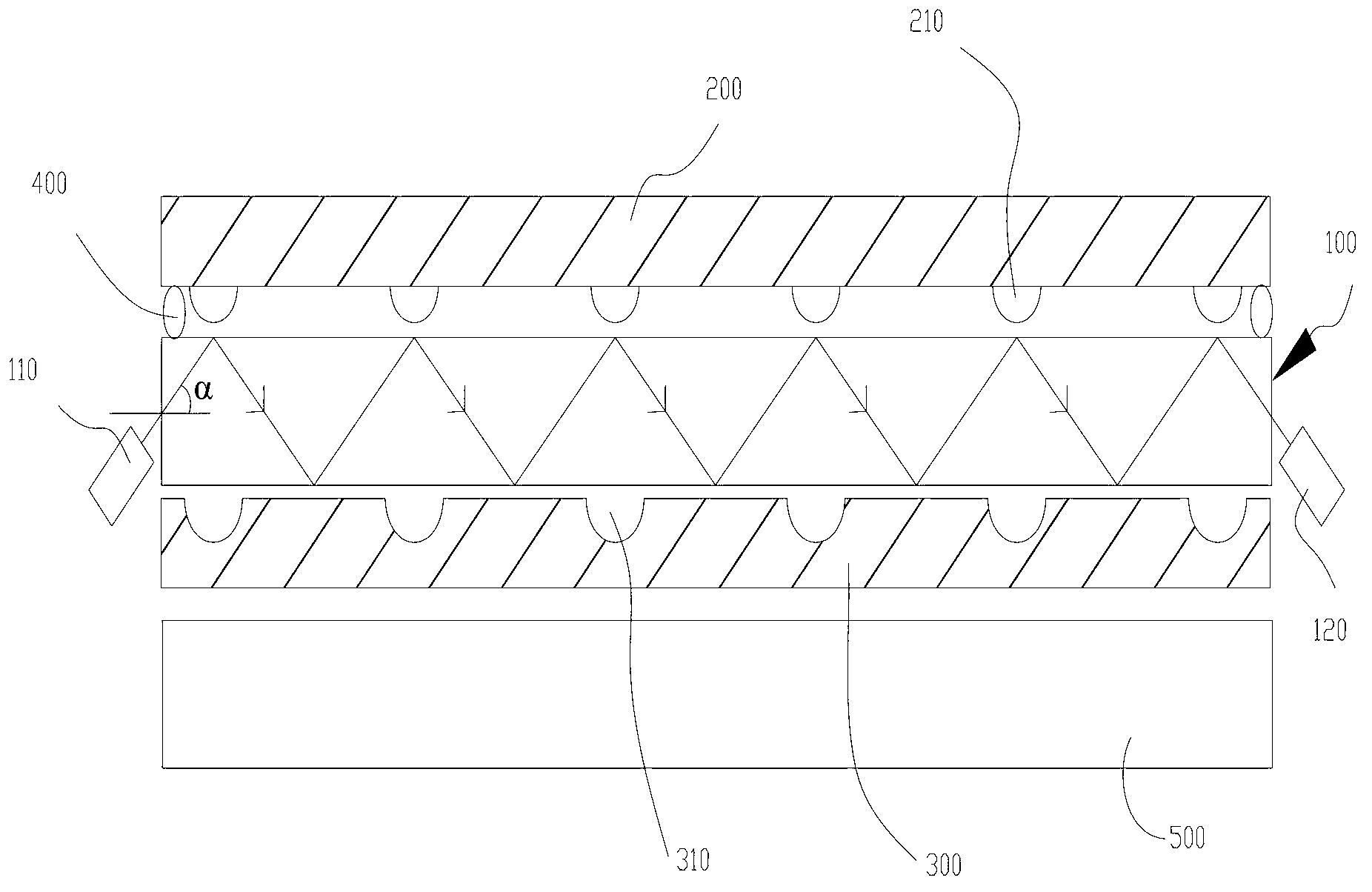
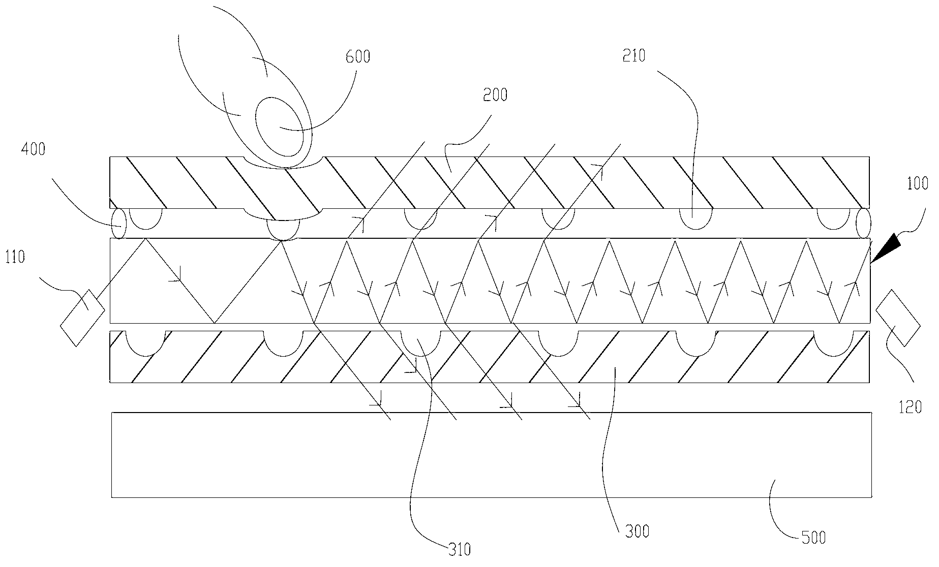
[0020] Please also refer to figure 1 and figure 2 , the optical touch screen of the present invention includes an optical reflective plate 100, a display screen 500, a detection control circuit (not shown in the figure) and at least one pair of optical emitting heads 110 and optical receiving heads 120, and the optical reflective plate 100 is arranged on the display screen 500 above, wherein, the optical emitting heads 110 in each pair are arranged on one side of the optical reflecting plate 100 according to the angle at which the incident light can be totally reflected inside the optical reflecting plate 100, and the corresponding optical receiving heads 120 in each pair are arranged according to The angle that can accept the incident light (after being reflected by the optical reflection plate 100 ) is set on the other side of the optical reflection plate 100 ...
PUM
 Abstract
Description
Claims
Application Information