Green luminous coating

A technology of luminescent paint and luminescent material, which is applied in luminescent paint, polyester paint, epoxy resin paint, etc., can solve the problem of high corresponding temperature measurement temperature, achieve the effect of simple method, reduce error, and improve temperature measurement accuracy

Inactive Publication Date: 2011-09-14
CHINA ACAD OF AEROSPACE AERODYNAMICS +1
View PDF0 Cites 0 Cited by
  • Summary
  • Abstract
  • Description
  • Claims
  • Application Information

AI Technical Summary

Problems solved by technology

[0010] The currently used phosphorescence temperature measurement technology has a relatively high temperature measurement area, and is more sensitive above 373K

Method used


Image

  • Green luminous coating
  • Green luminous coating
  • Green luminous coating

Examples


specific Embodiment

[0027] Specific examples are shown in the following table:

[0028]

[0029]

[0030] Only take Example 4 as an example to briefly describe the preparation process of the present invention, and the principles of the preparation process of other embodiments are the same.

[0031] (1) The chemical formula prepared by the traditional high-temperature solid-phase method is: 10CaO.3Si 2 o 7 .Cl 2 :aEu 2+ (a=0.1) Luminescent material.

[0032] The raw material is calcium oxide or carbonate, oxalate, nitrate, etc. that can generate calcium oxide after heating; silicon dioxide, ammonium chloride, europium trioxide or substances that can generate europium trioxide during the synthesis process. Weigh the raw materials according to the stoichiometric ratio, grind and mix them evenly, burn the raw materials at 900-1500°C for 1-20 hours in a reducing atmosphere, and cool them out of the furnace to obtain the green luminescent material 10CaO.3Si 2 o 7 .Cl 2 :0.1Eu 2+ .

[003...


PUM

PropertyMeasurementUnit
emission peakaaaaaaaaaa
wavelengthaaaaaaaaaa

Abstract

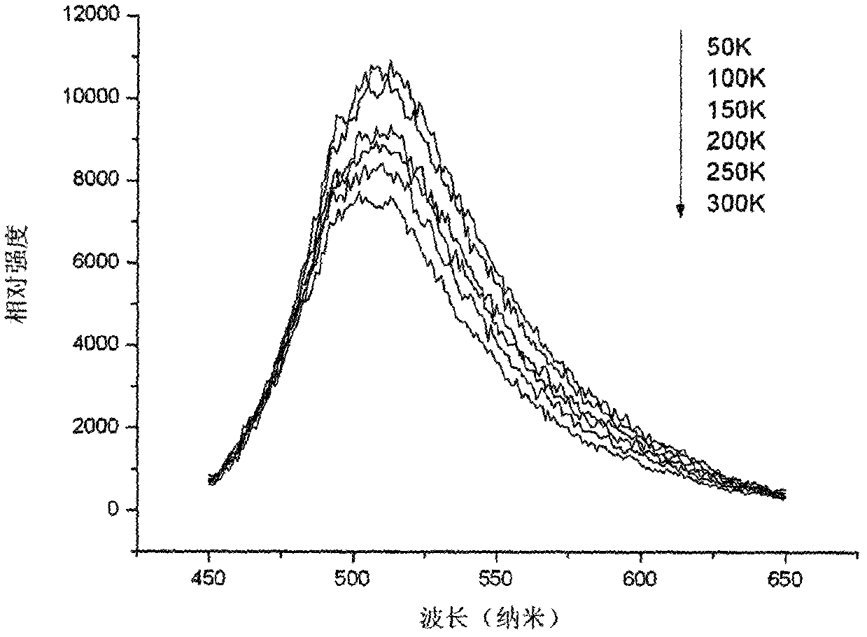
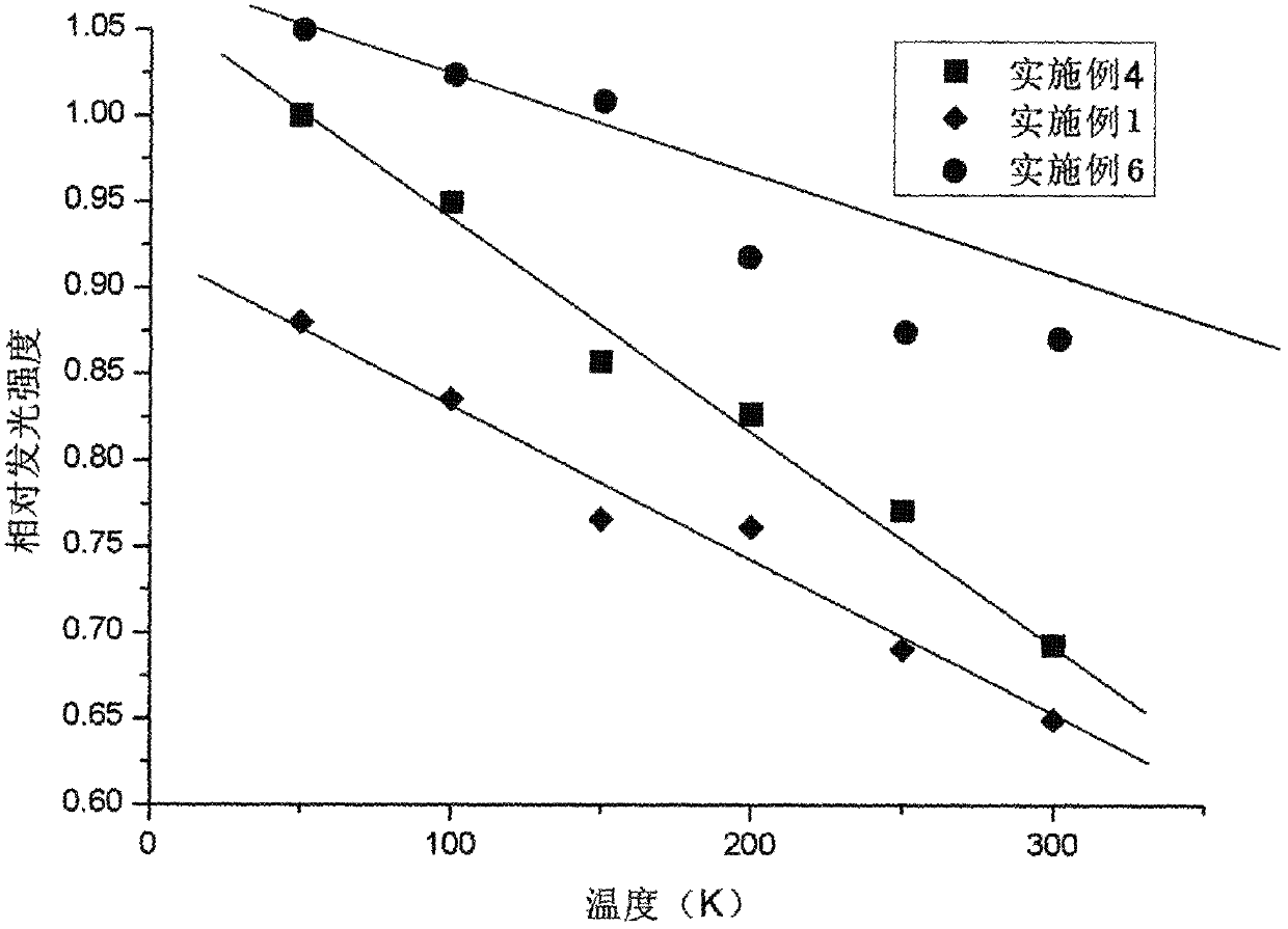
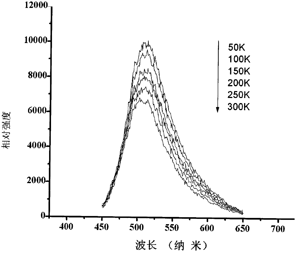
The invention discloses a green luminous coating which comprises a substrate coating and a luminous material. The chemical formula of the luminous material is 10CaO.3Si2O7.Cl2:aEu<2+>, wherein the atomic ratio a is 0.001-1; the substrate coating is a coating through which nanometer light with the wavelength of less than 460 nanometers can pass; the mass percentage of the luminous material is 3-70 percent; and the mass percentage of the substrate coating is 30-97 percent. The luminous material, i.e., 10CaO.3Si2O7.Cl2:aEu<2+> which is sensitive at the temperature of 50-300 K is adopted; the temperature of 50-300 K can be reflected accurately according to the linear relation between the green light emitting intensity of the luminous material along with the temperature and the temperature; and the green luminous coating can be applied to phosphorescent light temperature measurement in the temperature range of 50-300 K.

Description

technical field [0001] The invention relates to a green luminescent paint, which is used for non-contact temperature testing and belongs to the technical field of luminous paint. Background technique [0002] In the field of aerospace, with the development of high-speed aircraft, aerodynamic thermodynamics is facing a series of aerodynamic heat transfer problems that need to be solved urgently. For example, separation and vortex flow caused by mutual interference between shock wave and boundary layer; turbulent flow structure; supersonic / hypersonic flow characteristics around protrusions; three-dimensional separation flow at high angle of attack, etc. In the field of heat transfer in engineering thermophysics, research on enhanced heat transfer, jet cooling technology, and heat transfer phenomena in complex structures also encountered some complex heat transfer problems. The study of these complex phenomena requires a comprehensive understanding of the heat exchange process...

Claims


Application Information

Patent Timeline
Patent Type & Authority Applications(China)
IPC IPC(8): C09D5/22C09D183/04C09D133/00C09D163/00C09D167/00C09D161/20C09D167/08C09D161/06G01K11/20
Inventor 李锋张洪杰毕志献李成宇伍超华师丽丽韩曙光苏锵李睿劬刘训华
Owner CHINA ACAD OF AEROSPACE AERODYNAMICS
Why Eureka
Try Eureka