Phototube exposing type photoelectric effect experimental instrument for modulating light emitting diode (LED) light source by using alternating current

A technology of LED light source and photoelectric effect, which is applied in the field of experimental instruments, can solve problems such as inability to carry out experiments, irregular fluctuations in output signals, and unfavorable measurement results, and achieve the effects of avoiding congenital defects, improving stability, and avoiding zero-point drift

Inactive Publication Date: 2013-04-03
JIANGSU HUISHUO SCI EQUIP INSTR
View PDF0 Cites 0 Cited by
  • Summary
  • Abstract
  • Description
  • Claims
  • Application Information

AI Technical Summary

Problems solved by technology

[0002] Existing instruments for various photoelectric effect experiments (measurement of Planck's constant) have two common defects: 1. The photoelectric cells used in the experiment must be sealed in a light-shielding dark box
During the experimental measurement, only the light from a specific light source is allowed to irradiate the photoelectric tube. If the light from other light sources is irradiated on the photoelectric tube, it will interfere with the photoelectric tube’s reception of the light from the original specific light source, making the experiment impossible.
However, the photoelectric tube is sealed in a dark box and cannot be directly observed by the experimenter, which is not conducive to open teaching.
2. In the various existing photoelectric effect experiments (measurement of Planck's constant) instruments, the weak photocurrent generated by the photoelectric tube after being irradiated by light is measured only after multi-stage DC amplification, and the DC amplification circuit itself There is a congenital defect of zero drift, multi-stage DC amplification will cause irregular fluctuations in the final output signal, which is not conducive to obtaining stable measurement results

Method used


Image

  • Phototube exposing type photoelectric effect experimental instrument for modulating light emitting diode (LED) light source by using alternating current
  • Phototube exposing type photoelectric effect experimental instrument for modulating light emitting diode (LED) light source by using alternating current

Examples


Embodiment Construction

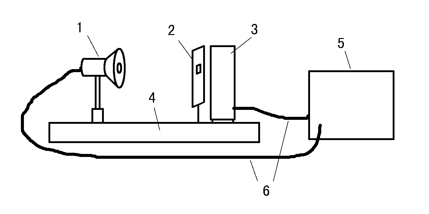
[0014] Will figure 1 The LED light source (1), the light blocking light bar (2), and the photoelectric cell (3) are installed on the installation base (4), and the first three are required to be kept on the same straight line. During the experiment, the LED light source (1) and the photoelectric cell (3) must be connected to the instrument host (5) through the signal cable (6).

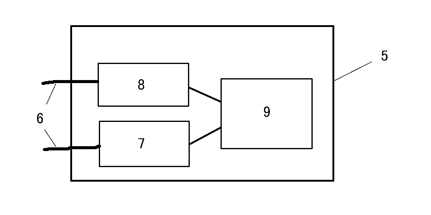
[0015] Will figure 2 The AC modulation circuit (7) and the AC micro-current detection and synchronous amplification circuit (8) inside the main unit (5) of the instrument are respectively connected via the signal cable (6) and figure 1 The LED light source (1) in the instrument is connected to the photocell (3), and at the same time, the AC modulation circuit (7) and the AC microcurrent detection and synchronous amplification circuit (8) inside the instrument host (5) are controlled by the measurement result display and control circuit ( 9) Control.


PUM


Abstract

Disclosed is a phototube exposing type photoelectric effect experimental instrument for modulating a light emitting diode (LED) light source by using alternating current. A phototube of the instrument uses the LED light source which is modulated by the alternating current during experimental measurement, the phototube of the instrument can be exposed to the natural environment light and can be observed by an experimenter directly during the measurement by the aid of the LED light source modulated by the alternating current, the alternating current micro-current detection and the simultaneous amplification circuit, other light sources can shine the phototube when the source light used for measurement shines the phototube, and measurement results of experiment are not interfered due to shining of other light sources. Besides, by the aid of the alternating current amplifying circuit for isolating the direct current, the zero drift defect of the direct current amplifying circuit is avoided, and the stability of measurement results can be improved greatly.

Description

technical field [0001] The invention relates to a photoelectric effect experimental instrument in physics, in particular to a photoelectric tube exposed photoelectric effect experimental instrument using an AC modulated LED light source. Background technique [0002] Existing instruments for various photoelectric effect experiments (measurement of Planck's constant) have two common defects: 1. The photoelectric cells used in the experiment must be sealed in a light-shielding dark box. During the experimental measurement, only the light from a specific light source is allowed to irradiate the photoelectric tube. If the light from other light sources is irradiated on the photoelectric tube, it will interfere with the photoelectric tube’s reception of the light from the original specific light source, making the experiment impossible. . However, the photoelectric tube is sealed in a dark box and cannot be directly observed by the experimenter, which is not conducive to open te...

Claims


Application Information

Patent Timeline
Patent Type & Authority Applications(China)
IPC IPC(8): G09B23/18
Inventor 周红兵钱仰德
Owner JIANGSU HUISHUO SCI EQUIP INSTR
Why Eureka
Try Eureka