Capacitor of lithium ion battery

A technology for lithium-ion batteries and capacitors, applied in electrolytic capacitors, capacitors, double-layer capacitors, etc., can solve the problems of large surface area, reduce energy density, consume large lithium ions, etc., achieve low self-discharge rate, enhance practicability, widen Effects of Using Temperature Range and Voltage Range

Inactive Publication Date: 2013-04-03
EVE ENERGY CO LTD
View PDF11 Cites 38 Cited by
  • Summary
  • Abstract
  • Description
  • Claims
  • Application Information

AI Technical Summary

Benefits of technology

This patented technology improves upon existing batteries by combining certain components into one component called an elec trolytes that can be used for both charge storage and energy transfer functions. These improvements include improved performance at extreme temperatures or voltages while maintaining good electrical properties such as long cycle life and fast charging capabilities. Additionally, this new design allows for more precise control over various factors like composition and concentration levels within the eletrodes' compositions during production processes. Overall, these technologies improve the overall quality and durability of Lithium Ion secondary cells.

Problems solved by technology

The patent text discusses the challenges faced by lithium-ion batteries and capacitors in meeting the increasing demands for high energy density and output power in modern society. It highlights the limitations of lithium-ion batteries in terms of rate performance, power density, and voltage range, which can lead to safety hazards. It also mentions the relatively low energy density and high self-discharge rate of capacitors. To address these challenges, the patent proposes a hybrid capacitor that combines the power storage principles of lithium-ion batteries and electric double-layer capacitors. However, the existing methods mentioned in the patent have drawbacks such as high cost, complexity, and low practicability. Another patent proposes a supercapacitor battery that combines the interface electric double layer and lithium-ion battery intercalation and deintercalation. However, it only partially solves the issue of lithium ion source and does not effectively increase the energy density. The use of activated carbon in supercapacitor batteries can further reduce the energy density. Overall, the technical problems addressed in the patent text include the need for high energy density and high output characteristics, as well as the limitations of existing storage devices in terms of rate performance, power density, and energy density.

Method used


Image

  • Capacitor of lithium ion battery
  • Capacitor of lithium ion battery
  • Capacitor of lithium ion battery

Examples


Embodiment 1

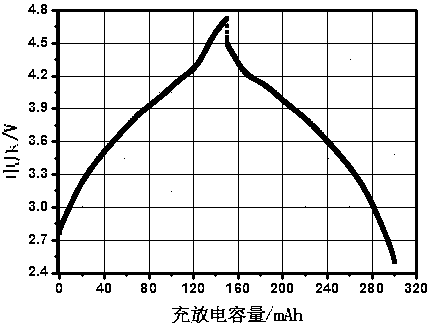
[0022] 1520 type (diameter 15.0mm, height 20.0mm) cylindrical lithium ion battery capacitor, the negative plate of the capacitor is composed of 50% hard carbon and 50% natural graphite (capacity percentage) as active material, and then combined with carboxymethyl fiber Soluble styrene-butadiene rubber binder, and superconducting acetylene black are mixed evenly, and deionized water is used as a solvent, stirred into a slurry, and coated on a 15-micron copper foil; the positive plate is made of 95% LiMn 2 o 4 and 5% activated carbon (volume percentage) to form the active material, and then mix it evenly with conductive graphite, superconducting acetylene black and polyvinylidene fluoride binder, use N-methylpyrrolidone as a solvent, stir into a slurry, and coat It is made on 20 micron aluminum foil; the positive and negative electrodes are separated by polypropylene-polyethylene-polypropylene microporous membrane and wound to form a core. The negative ear is drawn to the posit...

Embodiment 2

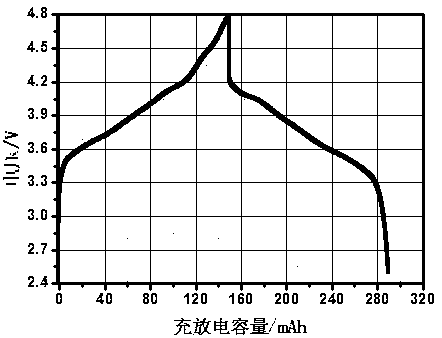
[0024] 1520 type (diameter 15.0mm, height 20.0mm) cylindrical lithium ion battery capacitor, the negative plate of the capacitor is composed of 95% soft carbon and 5% modified graphite (capacity percentage) as active material, and then combined with carboxymethyl group Cellulose, soluble styrene-butadiene rubber binder, and superconducting acetylene black are mixed evenly, and deionized water is used as a solvent, stirred into a slurry, and coated on a 15-micron copper foil; the positive plate is made of 80% LiCoO 2 and LiNi 1 / 3 co 1 / 3 mn 1 / 3 o 2 The active material is composed of 20% activated carbon (volume percentage), and then mixed evenly with conductive graphite, superconducting acetylene black and polyvinylidene fluoride binder, using N-methylpyrrolidone as a solvent, stirred into a slurry, and coated It is made on 20 micron aluminum foil; the positive and negative electrodes are separated by polypropylene-polyethylene-polypropylene microporous membrane and wound to ...

Embodiment 3

[0026] 1520 (diameter 15.0mm, height 20.0mm) type cylindrical lithium ion battery capacitor, the negative plate of the capacitor is composed of 75% hard carbon and soft carbon mixed with 25% artificial graphite and natural graphite (capacity percentage) to form the active material , and then mixed with carboxymethyl cellulose, soluble styrene-butadiene rubber binder, and superconducting acetylene black, using deionized water as a solvent, stirred into a slurry, and coated on a 15-micron copper foil; The positive plate is made of 50% LiNi 0.8 co 0.2 o 2 And 50% activated carbon (volume percentage) to form the active material, then mix with conductive graphite, superconducting acetylene black and polyvinylidene fluoride binder, use N-methylpyrrolidone as solvent, stir into slurry, and coat It is made on 20 micron aluminum foil; the positive and negative electrodes are separated by polypropylene-polyethylene-polypropylene microporous membrane and wound to form a core. The nega...


PUM

PropertyMeasurementUnit
Diameteraaaaaaaaaa
Heightaaaaaaaaaa

Abstract

The invention relates to a capacitor of a lithium ion battery. The capacitor comprises a capacitor shell, an organic electrolyte arranged in the capacitor shell, a winding core formed by isolating a positive plate from a negative plate through an ion permeability microporous membrane and winding, wherein the positive plate and the negative plate are respectively connected with a positive lug and a negative lug and are led out by the positive lug and the negative lug to a positive end and a negative end of the capacitor shell. A negative active material comprises a material A and a material B, wherein the material A comprises at least one of hard carbon and soft carbon, the material B comprises at least one of natural graphite, modified graphite and synthetic graphite, the material A accounts for 50.0%-95.0% of the capacity percentage of the negative active material, and the material B accounts for 5.0%-50.0% of the capacity percentage of the negative active material. The capacitor has the high-energy density characteristic of the lithium ion battery and the high-power density characteristic of a double electric layer capacitor.

Description


Claims


Application Information

Patent Timeline
Owner EVE ENERGY CO LTD
Why Eureka
Try Eureka