
Grounding cable clamp

A technology of grounding cables and wire clamps, which is applied in the direction of circuits, connections, electrical components, etc., can solve the problems of easy loosening of screws, short service life, and inconvenient installation of grounding wires, and achieve stable and reliable connections, convenient and safe use, and clamping The effect of constant tension

Active Publication Date: 2013-04-03
GUANGZHOU PANYU CABLE WORKS
View PDF6 Cites 4 Cited by
  • Summary
  • Abstract
  • Description
  • Claims
  • Application Information

AI Technical Summary

Problems solved by technology

[0002] In today's society, it is very important to use electricity safely and ensure the safe and stable operation of the power grid. The poor connection of wires has brought a lot of trouble to people, and even has potential safety hazards.
The existing clamps are unevenly stressed on one side and easily deformed on one side. When the nut is tightened, it will slide to the left and right sides. It takes multiple adjustments to align, which increases the difficulty of operation; it cannot be self-locking, and the connection is not stable. Affected by thermal expansion and contraction, it is easy to loosen, the service life is short, and maintenance is frequent; the contact surface is small, professional tools are required, installation is inconvenient, and the versatility is poor. It is inconvenient to install the grounding wire when repairing the cable, and it cannot cause lightning discharge. Thunderstorm cable Vulnerable

Method used


Image

  • Grounding cable clamp
  • Grounding cable clamp
  • Grounding cable clamp

Examples


Embodiment 1

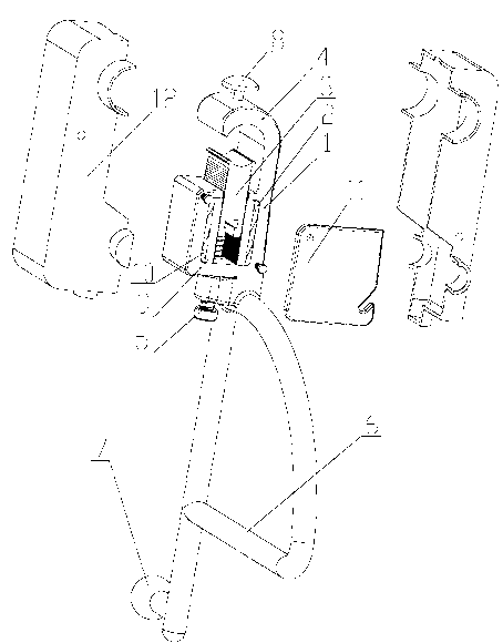
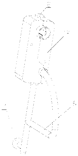
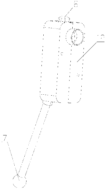
[0024] like figure 1 and figure 2 As shown, a grounding cable clamp includes a clamp body 1, a groove 2 is provided in the clamp body 1, a movable chuck 3 that can move up and down is embedded in the groove 2, and a clamp body 1 is fixedly connected with a The static chuck 4 opposite to the movable chuck 3 has a bolt hole under the clamp body 1, and an adjusting bolt 5 passes through the bolt hole and is fixedly connected with the wire clamp body 1, and connects with the movable chuck 3 at the same time. A grounding cable clamp is provided with a grounding connection device 6 . Among them, the ground connection device is preferably a structure with a horizontal rod, which is more convenient to connect the ground wire during construction, because the horizontal rod is more conducive to the clamping of the ground wire chuck, the force is uniform, the ground wire is firmly connected, and construction safety is ensured. One of the grounding cable clamps is provided with a disch...


PUM


Abstract

The invention discloses a grounding cable clamp comprising a cable clamp body provided with a groove. A movable clamp head capable of moving vertically is embedded into the groove. The cable clamp body is provided with a grounding connection device. A fixed clamp head opposite to the movable clamp head is fixedly connected above the cable clamp body, a bolt hole is arranged below the cable clamp body, and an adjustable bolt penetrates through the bolt hole to be fixedly connected with the cable clamp body while connectedly butts against the movable clamp head. Nonreturn sawteeth which is nonreturn down is arranged on one or two sides of the movable clamp head. Anti-loosing nonreturn sawteeth pieces are matched with the nonreturn sawteeth and arranged at outside of the nonreturn sawteeth of the movable clamp head. A pressure spring is arranged between the anti-loosing nonreturn sawteeth piece and the cable clamp body at at least one side. The movable clamp head and the anti-loosing nonreturn sawteeth pieces are pressed tightly by the pressure spring. The grounding cable clamp is high in universality, simple in structure, balanced in pressure, constant in clamping force, small in contact resistance, stable and reliable in connection, convenient for mounting of a grounding wire, convenient to use and safe to mount, and even can trigger lightning discharge so as to protect the cables.

Description

technical field [0001] The invention relates to a cable clamp, in particular to a grounding cable clamp. Background technique [0002] In today's society, it is very important to use electricity safely and ensure the safe and stable operation of the power grid. The poor handling of wire connections has brought a lot of trouble to people, and even has potential safety hazards. The existing clamps are unevenly loaded on one side and easily deformed on one side. When the nut is tightened, it will slide to the left and right sides. It requires multiple adjustments to align, which increases the difficulty of operation; it cannot be self-locking, and the connection is not stable. Affected by thermal expansion and contraction, it is easy to loosen, the service life is short, and maintenance is frequent; the contact surface is small, professional tools are required, installation is inconvenient, and the versatility is poor. It is inconvenient to install the grounding wire when repai...

Claims


Application Information

Patent Timeline
Patent Type & Authority Applications(China)
IPC IPC(8): H01R11/14H01R4/40H01R13/66
Inventor 胡超强尤占山覃丹王利江卢广业张仕宽申常伟
Owner GUANGZHOU PANYU CABLE WORKS
Learn More