Medium voltage power distribution cabinet

A power distribution cabinet and medium-voltage technology, which is applied in the field of medium-voltage power distribution cabinets, can solve problems such as troublesome and problematic current conduction functions, unreasonable industrial costs, etc.

Active Publication Date: 2013-04-03
SCHNEIDER ELECTRIC IND SAS
View PDF3 Cites 2 Cited by
  • Summary
  • Abstract
  • Description
  • Claims
  • Application Information

AI Technical Summary

Problems solved by technology

[0005] Moreover, these cabinets are capable of withstanding higher rated currents than the middle of a range that usually corresponds to the range of small consumptions, which leads to an unjustified industrial cost of such an adaptation
[000

Method used


Image

  • Medium voltage power distribution cabinet
  • Medium voltage power distribution cabinet
  • Medium voltage power distribution cabinet

Examples


Embodiment Construction

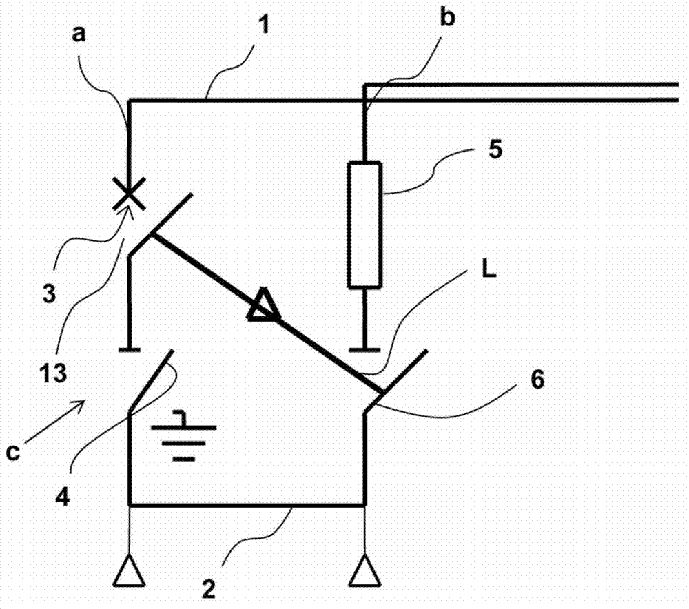
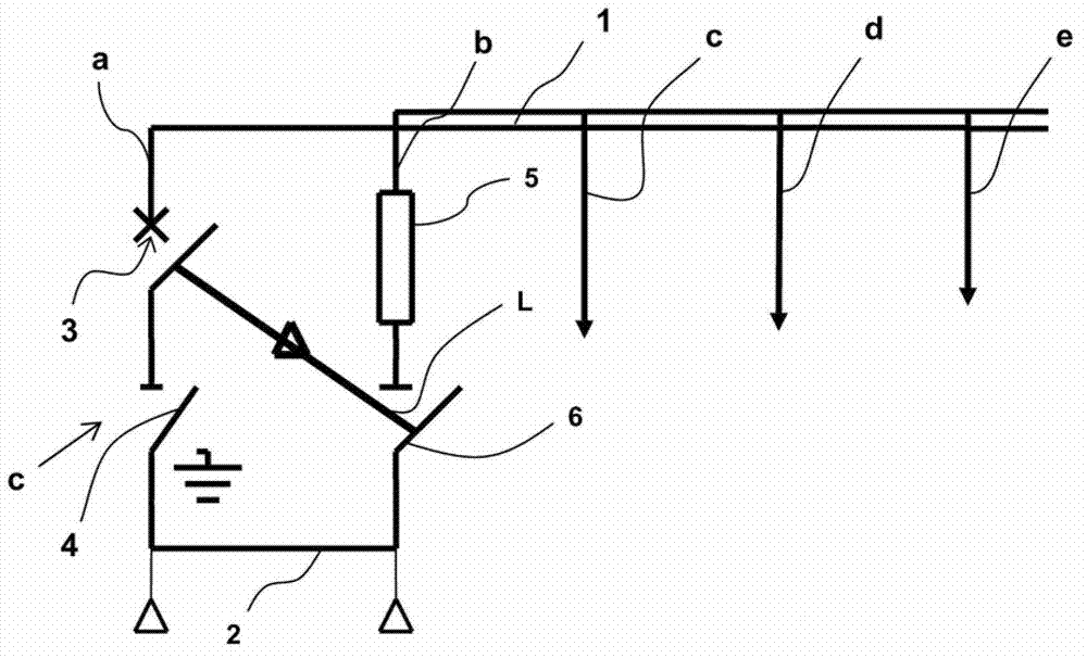
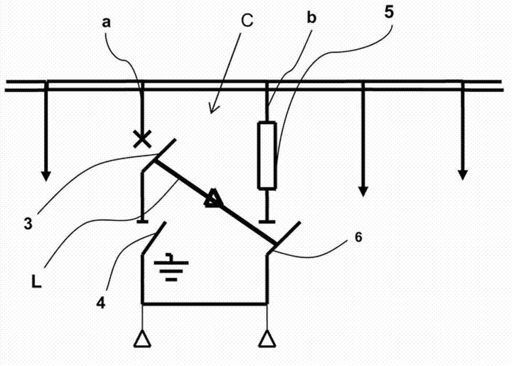
[0040] In said figure is represented a medium voltage distribution cabinet C according to the invention, which is designed to electrically connect two omnibus bars 1, 2 and to conduct a high rated current from a "standard" cabinet with a lower rated current , such as a current of 1250A in this particular embodiment. This cabinet C is designed to perform several functions, namely to enable current to flow between the busbars 1, 2; can occur) thereafter by the opening performed by the circuit breaker to perform the interruption of the current flow; and to perform the opening of the circuit so that the two parts of the power system can operate independently.

[0041] exist figure 1 , and according to a particular embodiment of the invention, this cabinet C comprises two branches or cabinets a, b arranged in parallel. A first cabinet a includes a circuit breaker 3 in series with an earthing switch 4 , which includes a vacuum box 13 ;

[0042] The first cabinet a has breaking an...


PUM


Abstract

The invention relates to a medium voltage power distribution cabinet. The medium voltage power distribution cabinet is designed to be mounted between the two parts of the circuit, in order to at least perform current flowing between the two parts and current interruption in case of electrical failure. The medium voltage power distribution cabinet is characterized by comprising a first cabinet (a) special for interrupting and forming the current, wherein the cabinet includes an electrical protector (3) for interrupting and forming the current; and a second cabinet (b) special for making the rated current pass through, wherein the cabinet includes a device (6) for conducting the rated current and the short circuit current before current interruption period by using the protector (3) and a device (6) for disconnecting the circuit, and the second cabinet (b) is designed to conduct the high rated current and a disconnection switch (6) is commanded by the electrical protector (3).

Description

technical field [0001] The invention relates to a medium-voltage electric distribution cubicle designed to be installed between two parts of an electrical circuit in order to perform at least the flow of current between said two parts And the function of current interruption in case of electrical failure. Background technique [0002] Switchboards of the above-mentioned type are known, for example as described in patent application FR 2 940 516 . The cabinet includes a switch or circuit breaker that also performs the function of a disconnect switch, and a selector in series with the switch (or circuit breaker) having at least two positions, one for current flow and one for ground. [0003] This cabinet is designed to conduct a current of 630 A and is therefore not suitable for conducting higher current levels such as eg 1250 A. [0004] When it is necessary to increase the rated current performance of such a cabinet, or any similar cabinet, huge investments and extensive c...

Claims


Application Information

Patent Timeline
IPC IPC(8): H02B1/24H02B1/30
CPCH01H9/26H01H31/10H01H33/14H01H33/143H01H33/16H01H33/6661
Inventor C.普雷夫J-P.柯苏珊
Owner SCHNEIDER ELECTRIC IND SAS
Why Eureka
Try Eureka