Drive device for vehicle opening/closing body

一种驱动装置、开闭体的技术,应用在机电装置、车辆部件、电动组件等方向,能够解决不能蜗轮旋转力传递等问题,达到成本降低、小型轻量化提高、控制逻辑器精简化的效果

Inactive Publication Date: 2013-04-03
MITSUBA CORP
View PDF5 Cites 12 Cited by
  • Summary
  • Abstract
  • Description
  • Claims
  • Application Information

AI Technical Summary

Problems solved by technology

[0006] In this way, since the driving device described in Patent Document 1 includes: a worm with a rotating shaft perpendicular to each other and a worm wheel (reduction mechanism), it is impossible to transmit the rotational force of the worm wheel to the worm

Method used


Image

  • Drive device for vehicle opening/closing body
  • Drive device for vehicle opening/closing body
  • Drive device for vehicle opening/closing body

Examples


Embodiment Construction

[0037] Next, the first embodiment of the present invention will be described in detail using the drawings.

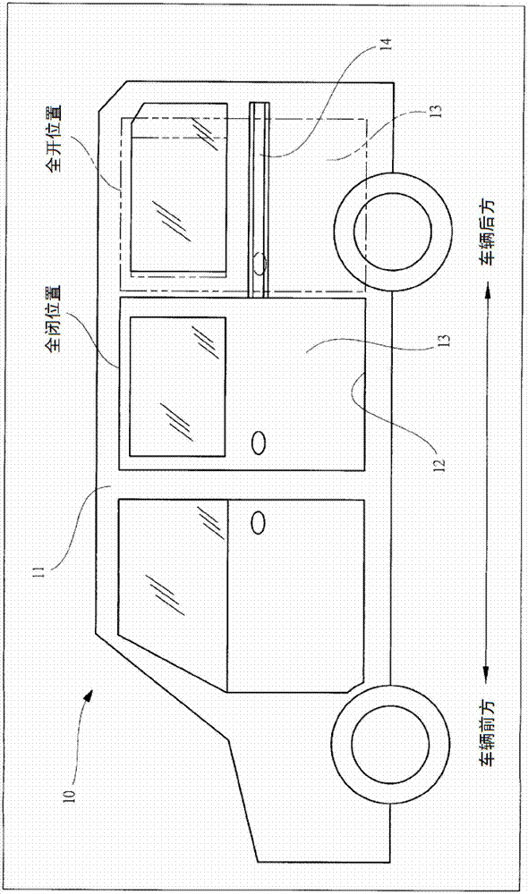
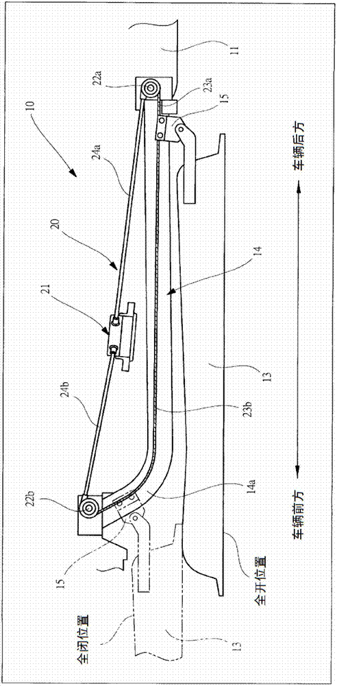
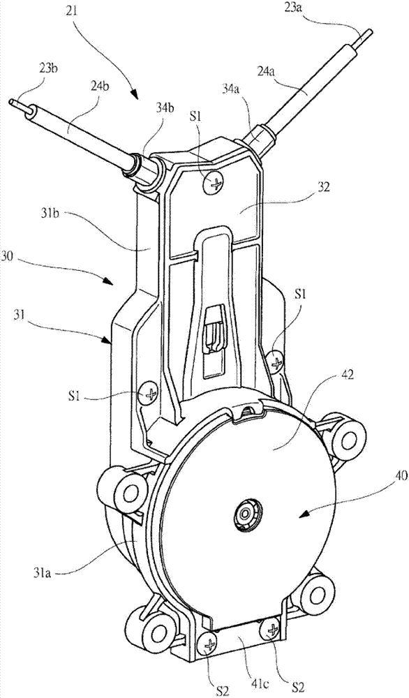
[0038] figure 1It is a side view of a vehicle equipped with the driving device of the present invention, figure 2 is a plan view showing the installation structure of the sliding door, image 3 is a perspective view showing the appearance of the drive unit, Figure 4 is a perspective view showing the reel unit and the motor unit, Figure 5 An exploded perspective view illustrating the detailed structure of the reel unit, Image 6 An exploded perspective view illustrating the coupling structure of the drum, damping member, and torque transmission member, Figure 7 is a sectional view showing the detailed structure of the motor unit, Figure 8 (a) is an explanatory diagram of the operation of the hypocycloid reducer of this embodiment, Figure 8 (b) is an explanatory diagram of the operation of another hypocycloid reducer (modified example).

[0039] figure 1 Th...


PUM


Abstract

A hypocycloid decelerator (70), whereby the revolutions of a flat motor (60) are decelerated and output to a drum, is provided between a drum and the flat motor (60), a rotor shaft part (65) that revolves at the same rotational velocity as that of the flat motor (60) is provided on the same shaft as the drum and on the flat motor (60) side, and a revolution output body (74) that outputs the revolutions of the decelerated flat motor (60) is provided on the same shaft as the drum at the drum side. By providing the rotor shaft part (65) and the revolution output body (74) on the same shaft as the drum, rotational force can be conveyed in both directions, from the rotor shaft part (65) to the revolution output body (74) and from the revolution output body (74) to the rotor shaft part (65). As a result, it is possible to eliminate a magnetic clutch and achieve a drive device that is smaller and more lightweight, and because the wiring and control logic for the magnetic clutch are not needed, the cost of the drive device is also reduced.

Description

technical field [0001] The present invention relates to a drive device for an opening and closing body for a vehicle that drives an opening and closing body provided on a vehicle body to open and close. Background technique [0002] Conventionally, vehicles such as station wagons and vans are provided with sliding doors (opening and closing bodies) that slide along the front and rear directions of the vehicle on the side of the vehicle body. Carry out passenger take-off and cargo loading and unloading. Such a sliding door is usually manually opened and closed. In recent years, a driving device for opening and closing the sliding door is installed near the sliding door of the vehicle body, and there are many vehicles that automatically open and close the sliding door by driving the driving device. is common. [0003] As the driving device for opening and closing the sliding door, there is a so-called rope-type driving device, which connects the rope connected to the sliding...

Claims


Application Information

Patent Timeline
Patent Type & Authority Applications(China)
IPC IPC(8): B60J5/06B60J5/04E05F15/14H02K7/10H02K7/116
CPCE05F15/145H02K7/1004H02K5/24E05F15/146E05Y2900/531H02K7/116H02K1/30H02K1/2733B60J5/047E05F15/646E05F15/643Y10T74/18832
Inventor 冈田光弘中岛龙一斋藤龙之山口善太郎
Owner MITSUBA CORP
Why Eureka
Try Eureka