Rotary die core control device for unscrewing metallic die

A control device and a technology for rotating molds, applied in the field of rotating mold core control devices, can solve problems such as prolonging cycle time, and achieve the effect of shortening cycle time

Active Publication Date: 2013-04-10
FANUC LTD
View PDF4 Cites 1 Cited by
  • Summary
  • Abstract
  • Description
  • Claims
  • Application Information

AI Technical Summary

Problems solved by technology

When the rotating core returns to the "core original position 100" by the rotation of the symbol 210 in the forward direction, the backlash can be reduced, but there is a problem of prolonging the cycle time

Method used


Image

  • Rotary die core control device for unscrewing metallic die
  • Rotary die core control device for unscrewing metallic die
  • Rotary die core control device for unscrewing metallic die

Examples


Embodiment Construction

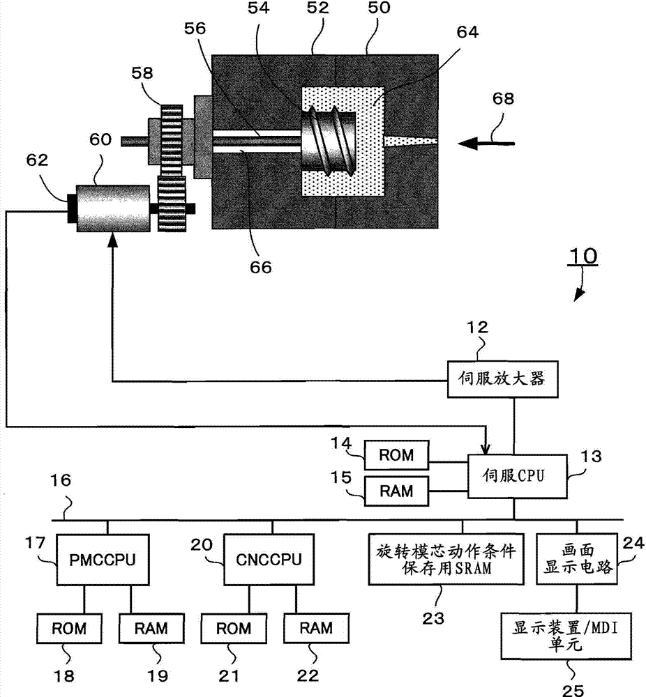
[0026] First, a schematic structure of a conventional injection molding machine (not shown) will be described. The injection molding machine has a clamping part and an injection part on the machine table. The injection part heats the molten resin material (pellet) and injects the molten resin into the cavity of the mold. Install the nozzle on the front end of the injection cylinder, and insert the screw through the injection cylinder. A hopper for supplying a resin material into the injection cylinder is attached to the upper portion of the injection cylinder.

[0027] The mold clamping section mainly opens and closes molds (fixed side molds, movable side molds). The mold clamping section includes a fixed plate on which the fixed side mold is mounted, a movable plate on which the movable side mold is mounted facing the fixed side mold, and a servo for opening and closing the mold that moves the movable plate forward and backward in the direction of the injection section. A ...


PUM


Abstract

The invention provides a rotary die core control device for unscrewing a metallic die. When an inject molding product with a screw portion from the metallic die, the rotary die core control device obtains a first rotation number for a rotary die core returning to a start position and rotating counterclockwise back to an original position of the die core and a second rotation number for the rotary die core returning to the start position and rotating clockwise back to an original position of the die core, compares the first rotation number and the second rotation number. When the first rotation number is greater than the second rotation number, the die core rotates counterclockwise back to the original position of the die core. On the other hand, when the first rotation number is smaller than the second rotation number, the die core rotates clockwise back to the original position of the die core. In such a treatment, the cycle time of pulling out a molded product from a metallic die is shortened.

Description

technical field [0001] The present invention relates to a rotary core control device for an unscrewing mold used in an injection molding machine, and more particularly to a device for controlling a servo motor to drive an unscrewing mold for molding a molded product having a screw portion. Rotary core control device for rotary core. Background technique [0002] In the snap-off metal mold with the structure of rotating the core to pull out the screw-shaped molded product injection-molded in the metal mold, oil is used for the rotational power of the core (rotary core) Although there is a method of pressure driving or air driving, there is also a method of using a servo motor (refer to Japanese Patent Application Laid-Open No. 4-47914). The servo motor-type rotary core is cleaner than other driving methods, and is suitable for molding in a clean environment such as molding of medical products. [0003] In addition, since the servo motor-type rotary mold core is also excelle...

Claims


Application Information

Patent Timeline
IPC IPC(8): B29C45/40B29C45/76
CPCB29C45/64B29C2945/76936B29C45/76B29C2945/76421B29C45/178B29C2945/76093B29C45/2618B29C45/44B29C2945/76264
Inventor 内山辰宏松尾明贤
Owner FANUC LTD
Why Eureka
Try Eureka