Manufacture method of box-shaped structural main beam made from composite material

A composite material and manufacturing method technology, applied in the field of composite material processing, can solve the problems of small selection range, small pressure, unable to reach the forming pressure of the main beam of the laminate, and achieve the effect of improving quality and reducing the possibility of looseness

Active Publication Date: 2013-04-10
JIANGXI HONGDU AVIATION IND GRP
View PDF4 Cites 37 Cited by
  • Summary
  • Abstract
  • Description
  • Claims
  • Application Information

AI Technical Summary

Problems solved by technology

This forming method is likely to cause a large area of ​​looseness in the web area of ​​the part, which seriously affects the product quality. After analysis: the main reason is that the material used for the male and female molds of the part is 45# steel, and the thermal expansion of the mold during the heating process The coefficient difference is small, and the pressure on the parts during the resin gelation period is relatively small, which cannot reach the molding pressure required for the main beam of the laminate during the curing process
[0004] At present, composite material parts such as this kind of middle hollow and thin-walled box-shaped structure are usually formed by thermal expansion molding. The product exerts pressure, but this molding process has strict requirements on the material of the male mold (core mold), mainly because the selected mold material requires its expansion performance to match the resin gel time of the composite material product, that is, in the composite material product The resin time period can generate the required expansion pressure, and the selection range of this material is small

Method used


Image

  • Manufacture method of box-shaped structural main beam made from composite material
  • Manufacture method of box-shaped structural main beam made from composite material

Examples


Embodiment Construction

[0018] A method for manufacturing a main girder of a composite material box structure provided by the present invention will be further explained below in conjunction with the accompanying drawings.

[0019] The steps of the manufacturing method of a kind of composite material box-shaped structure girder provided by the present invention are as follows:

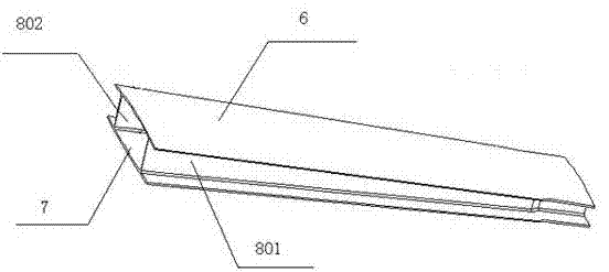
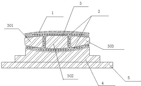
[0020] A. According to the structure of the main girder of the composite material box structure (such as figure 1 shown) to make the male mold 3, the female mold 4 and the auxiliary tooling equalizing plate 1. That is, the lower surface of the auxiliary tooling pressure equalizing plate 1 is the structure and curvature of the upper surface of the first cover plate 6 . The male mold 3 is composed of the first male mold 301 , the second male mold 302 and the third male mold 303 to form the structure and layout of the first side plate 801 and the second side plate 802 . The upper surface of the female mold 4 forms the structur...


PUM


Abstract

The invention relates to a manufacture method of a box-shaped structural main beam made from a composite material. The method comprises the following steps of: A, manufacturing a male mold, a female mold and an assistant tooling balance press plate; B, paving and gluing a prepreg of the composite material on the male mold, and vacuumizing and previously compacting under the normal temperature; C, laying the previously-compacted composite material on the female mold; D, combining the assistant tooling balance press plate, the male mold and the female mold from top to bottom, and packaging in a vacuum bag; E, putting the vacuum bag into a hot-press tank for vacuumizing and checking the air impermeability; and F, rising and keeping the temperature of the hot-press tank, keeping the pressure and rising the temperature after the tank is pressured, keeping the pressure and the temperature, cooling, releasing the pressure, and removing the male mold, the female mold, the assistant tooling balance press plate and a substrate to finally obtain the box-shaped structural main beam made from the composite material. According to the manufacture method, each molded surface region of the prepreg of the composite material can be pressured within a resin gel time, and the loosing of parts caused by the small pressure can be avoided.

Description

technical field [0001] The invention belongs to the field of composite material processing, and in particular relates to a method for manufacturing a main girder of a composite material box-shaped structure. Background technique [0002] Such as figure 1 As shown in the figure, the main girder of a composite laminate box structure is a box structure in which the opening gradually narrows from the end to the other end, and the first cover plate (6) and the second cover plate (7) are curved surfaces. pieces. Its specific structure is: the structure of the first cover plate (6) and the second cover plate (7) is an isosceles trapezoid, and the waist length of the first cover plate (6) and the second cover plate (7) is 980mm , the lower bottom is 160mm, the upper bottom is 100mm, and the first side plate (801) and the second side plate (802) gradually transition from a height of 54mm to a box-shaped structure with a height of 25 mm. [0003] The box structure of composite mat...

Claims


Application Information

Patent Timeline
Patent Type & Authority Applications(China)
IPC IPC(8): B29C70/34
Inventor 黄红初吴平马军万建平鄢和庚李跃殷俊马闪红
Owner JIANGXI HONGDU AVIATION IND GRP
Why Eureka
Try Eureka