Manipulator and substrate transfer device
A technology for substrate handling and manipulators, applied to manipulators, conveyor objects, transportation and packaging, etc., can solve problems such as inability to neutralize static electricity efficiently, and achieve the effect of efficient static removal
- Summary
- Abstract
- Description
- Claims
- Application Information
AI Technical Summary
Problems solved by technology
Method used
Image
Examples
no. 1 approach )
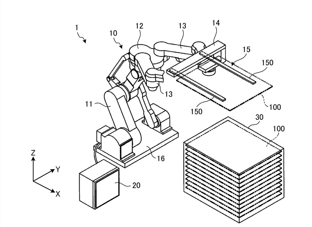
[0056] First, use figure 1 A configuration example of a substrate transfer system including the robot arm and the substrate transfer device according to the first embodiment will be described. figure 1 It is a diagram showing a configuration example of a substrate transfer system 1 including the robot 15 and the substrate transfer device 10 according to the first embodiment.
[0057] Also, for ease of understanding, the figure 1 A three-dimensional Cartesian coordinate system including the Z-axis with the positive direction vertically upward is illustrated in . The Cartesian coordinate system is sometimes also shown in other figures used in the following description.
[0058] Such as figure 1 As shown, the substrate transfer system 1 has a substrate transfer device 10 , a controller 20 and a cassette 30 .
[0059] The substrate transfer device 10 is a device that takes out and puts in and transfers the substrates 100 stored in the cassette 30 in multiple layers one by one....
no. 2 approach )
[0124] Next, use Figure 9A A configuration example of the manipulator 15A according to the second embodiment will be described. Figure 9A It is a figure which shows the structural example of the manipulator 15A which concerns on 2nd Embodiment.
[0125] In addition, since the manipulator 15A according to the second embodiment is mainly different from the manipulator 15 according to the first embodiment in the structure of piping, Figure 9A Only components related to the piping are shown in , and illustration of other components is omitted. In addition, the same reference numerals are assigned to the same components as those of the manipulator 15 according to the first embodiment.
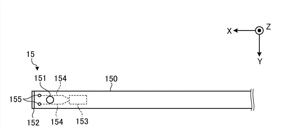
[0126] Such as Figure 9A As shown, the manipulator 15A according to the second embodiment includes a pipe 154A extending from the static eliminator 153 to the outside of the fork 150 , and a discharge hole 155 disposed on the pipe 154A.
[0127] The pipe 154A is exposed to the outside of the...
no. 3 approach )
[0134] Next, use Figure 9B A configuration example of the manipulator 15B according to the third embodiment will be described. Figure 9B It is a figure which shows the structural example of the manipulator 15B which concerns on 3rd Embodiment.
[0135] In addition, the manipulator 15B according to the third embodiment is mainly different from the manipulator 15A according to the second embodiment in the direction in which the discharge holes are arranged. Figure 9B In FIG. 2 , only components related to the above-mentioned ejection holes are shown, and illustration of other components is omitted. In addition, the same reference numerals are attached to the same components as those of the manipulator 15 according to the first embodiment and the manipulator 15A according to the second embodiment.
[0136] Such as Figure 9B As shown, the manipulator 15B according to the third embodiment includes a pipe 154B extending from the static eliminator 153 to the outside of the for...
PUM
 Abstract
Description
Claims
Application Information
 - R&D
- Intellectual Property
- Life Sciences
- Materials
- Tech Scout
- Unparalleled Data Quality
- Higher Quality Content
- 60% Fewer Hallucinations
Browse by: Latest US Patents, China's latest patents, Technical Efficacy Thesaurus, Application Domain, Technology Topic, Popular Technical Reports.
© 2025 PatSnap. All rights reserved.Legal|Privacy policy|Modern Slavery Act Transparency Statement|Sitemap|About US| Contact US: help@patsnap.com


