
Automatic positioning valve of hydraulic rotary device, rotary hydraulic system and engineering machinery

A slewing device and hydraulic system technology, applied in the direction of fluid pressure actuating device, mechanical equipment, servo motor, etc., can solve the problems of bumping and damage to the rotating working body, delaying the operation time, and difficulty in stopping the slewing mechanism to the target position. Practical, accurate positioning effect

Active Publication Date: 2015-04-15
ZOOMLION HEAVY IND CO LTD
View PDF6 Cites 0 Cited by
  • Summary
  • Abstract
  • Description
  • Claims
  • Application Information

AI Technical Summary

Problems solved by technology

However, due to the proficiency of manual operation and the poor visibility at night and in foggy days, it is difficult for the rotary mechanism to accurately stop at the target position, thus delaying the operation time and easily causing bump damage to the rotary working body
In addition, due to the large inertia of the slewing mechanism, it is difficult to brake the slewing mechanism and it is difficult to stop at the target position

Method used


Image

  • Automatic positioning valve of hydraulic rotary device, rotary hydraulic system and engineering machinery
  • Automatic positioning valve of hydraulic rotary device, rotary hydraulic system and engineering machinery
  • Automatic positioning valve of hydraulic rotary device, rotary hydraulic system and engineering machinery

Examples


Embodiment Construction

[0038] Specific embodiments of the present invention will be described in detail below in conjunction with the accompanying drawings. It should be understood that the specific embodiments described here are only used to illustrate and explain the present invention, and are not intended to limit the present invention.

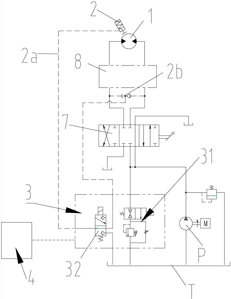
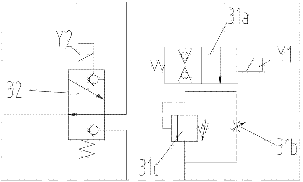
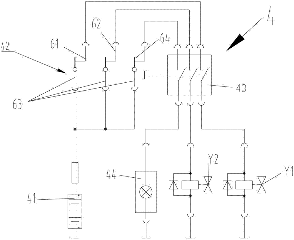
[0039] First of all, it needs to be explained that the present invention relates to the field of hydraulic control, and the present invention figure 1 and figure 2 Only hydraulic schematic diagrams are shown in , and for those skilled in the art, the same hydraulic connection principle can be realized by various mechanical entity structures. For example, the on-off valve 31a and the flow control valve 31b in the deceleration valve 31 can be connected through a pipeline or form an integrated composite valve, and the deceleration valve 31 and the brake valve 32 in the automatic positioning valve 4 can form a single integrated valve. Type composite valve is conv...


PUM


Abstract

The invention discloses an automatic positioning valve of a hydraulic rotary device. The hydraulic rotary device is braked by a rotary brake device. The automatic positioning valve comprises a speed reduction valve and a brake valve, wherein the speed reduction valve can be used for controlling the hydraulic rotary device to reduce the speed; and the brake valve can be used for controlling the rotary brake device to brake the hydraulic rotary device. The invention further discloses a rotary hydraulic system using the automatic positioning valve, and the rotary hydraulic system is used for controlling the rotary mechanism to rotate. The invention further discloses engineering machinery using the rotary hydraulic system. Through the technical scheme, as the automatic positioning valve comprises the speed reduction valve and the brake valve, the hydraulic rotary device can be decelerated firstly and then is braked when a rotary mechanism is required to stop in a target position, the inertial force of the rotary mechanism is reduced, the hydraulic rotary device can be accurately stopped in the target position, the accurate positioning action of the rotary mechanism is guaranteed, and the practicality of the corresponding engineering machinery is improved.

Description

technical field [0001] The invention relates to the field of automatic positioning of a hydraulic rotary device, in particular to an automatic positioning valve for a hydraulic rotary device, a rotary hydraulic system using the automatic positioning valve, and an engineering machine using the rotary hydraulic system. Background technique [0002] At present, the slewing mechanism is widely used in many construction machinery, such as the boom slewing mechanism of cranes and pump trucks, and the cab slewing mechanism. These slewing mechanisms need to be able to be accurately positioned in use so as to perform corresponding operations conveniently and accurately. In the prior art, the slewing mechanism is usually driven by a hydraulic slewing device such as a hydraulic motor to turn. In addition, in some slewing mechanisms with a small slewing range, the oil cylinder rack and gear can also be used to drive the slewing mechanism. . When the positioning of the slewing mechanis...

Claims


Application Information

Patent Timeline
Patent Type & Authority Patents(China)
IPC IPC(8): F15B13/04F15B11/02
Inventor 谢强于岩成刘绪清佘丽华李超
Owner ZOOMLION HEAVY IND CO LTD
Learn More