
Light source module, liquid crystal display device and neon lamp display device

A technology of a liquid crystal display device and a light source module, which is applied in the field of optics and can solve problems such as difficulty in applying side-entry backlight modules, unsuitability for thin design, and increased cost of backlight modules, and achieve low color gamut and penetration Low efficiency, simple structure, and the effect of improving the color gamut

Inactive Publication Date: 2013-04-10
BOE TECH GRP CO LTD
View PDF5 Cites 56 Cited by
  • Summary
  • Abstract
  • Description
  • Claims
  • Application Information

AI Technical Summary

Problems solved by technology

In order to make the color gamut of the liquid crystal display device exceed 100%, LEDs composed of three RGB chips are often used, or a group of LEDs is formed by separate R, G, and B three LEDs, but this method generally requires a certain amount of mixing. Light distance, so it is usually only used in direct-type backlight modules, and it is difficult to apply to side-type backlight modules; at the same time, this method not only doubles the cost of the backlight module, but is also not suitable for thin design

Method used


Image

  • Light source module, liquid crystal display device and neon lamp display device
  • Light source module, liquid crystal display device and neon lamp display device
  • Light source module, liquid crystal display device and neon lamp display device

Examples


Embodiment 1

[0041] This embodiment relates to a light source module, and the light source module is applied in the field of liquid crystal display as a backlight module and a liquid crystal display device including the backlight module.

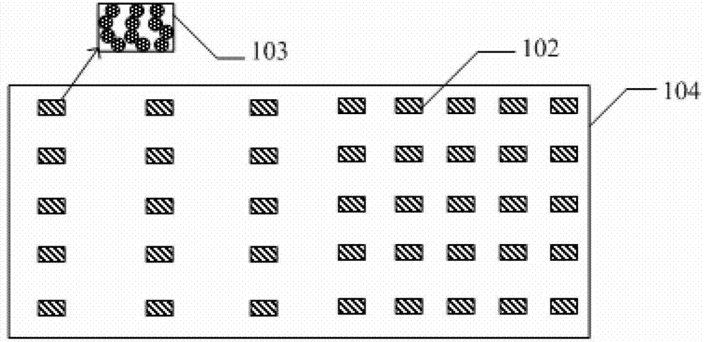
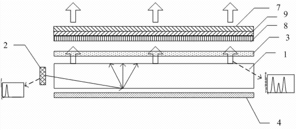
[0042] Such as figure 1As shown, the light source module includes a light guide plate 1 (Light Guide Plate, LGP for short) and a light-emitting unit 2 arranged on one side of the light guide plate. The light guide plate 1 includes a main body 101 and dots 102 arranged on the main body. The dots 102 are doped with quantum dot material 103 , and the quantum dot material is excited by the light of the light emitting unit 2 to emit light of a specific wavelength.

[0043] Wherein, the main body in the light guide plate 1 is plate-shaped, and the main body is formed of a transparent material, and the transparent material is PC (Polycarbonate, polycarbonate) or PMMA (Polymethyl Methacrylate, polymethyl methacrylate); The network dots include ink and a scatter...

Embodiment 2

[0057] This embodiment relates to a light source module, and the light source module is applied in the field of lighting, specifically, in the field of decorative display for neon light display.

[0058] Traditional neon lights are made of glass after firing. The glass tube can be bent into any shape. Different types of glass tubes are filled with different inert gases. Depending on the electrode tips set at both ends of the glass tube, the glass lamp will be turned under a high-voltage electric field. The rare inert gas in the tube is ignited, so as to obtain colorful and multi-color IPL display effects.

[0059] However, because traditional neon lights contain heavy metals such as mercury, they may cause environmental pollution, and the use of high-voltage electric fields is likely to bring safety hazards. Therefore, with the development of display technology, the burden of realizing neon light display has gradually shifted to the use of LED lights as light sources. Since th...


PUM

PropertyMeasurementUnit
diameteraaaaaaaaaa
diameteraaaaaaaaaa
diameteraaaaaaaaaa

Abstract

The invention belongs to an optical field and particularly relates to a light source module, a liquid crystal display device comprising the light source module, and a neon lamp display device comprising the light source module. The light source module comprises a light-emitting unit and a light guide board; the light guide board comprises a main body and lattice points arranged on the main body; a quantum dot material is doped in the lattice points; the quantum dot material is stimulated by light of a light-emitting unit to emit light with a specific wavelength. The display color gamut of the liquid crystal display device applying the light source module and the neon lamp display device can be greatly improved.

Description

technical field [0001] The invention belongs to the field of optics, and in particular relates to a light source module, a liquid crystal display device including the light source module, and a neon light display device including the light source module. Background technique [0002] The liquid crystal itself does not emit light. Therefore, a backlight module (Back Light Module) is used in the liquid crystal display panel (Liquid Crystal Display Panel) to provide a uniform and high-brightness light source for the liquid crystal panel. Generally speaking, the backlight module can be divided into side-type backlight module and direct-type backlight module according to the position of the light source in the backlight module, wherein the light source in the side-type backlight module is located on the side of the display panel. , the light source in the direct-lit backlight module is located at the bottom of the display panel. [0003] The side-type backlight module is assembl...

Claims


Application Information

Patent Timeline
Patent Type & Authority Applications(China)
IPC IPC(8): F21S8/00F21V8/00G02F1/13357G09F13/22
Inventor 蒋文杰张凯亮赵星星
Owner BOE TECH GRP CO LTD
Learn More