
Maxim intensity projection method based on enhanced visual perception

A technology of maximum density and visual perception, applied in the field of visual perception, can solve the problems of affecting illumination, loss of background compensation information, and the lack of orientation information of features in the resulting image, so as to enhance visual perception, enrich depth information and shape information, and ensure density. The effect of attribute similarity and spatial proximity

Active Publication Date: 2013-04-10
ZHEJIANG UNIV
View PDF2 Cites 7 Cited by
  • Summary
  • Abstract
  • Description
  • Claims
  • Application Information

AI Technical Summary

Problems solved by technology

Although the MIP algorithm can meet the specific needs of users to a certain extent, there are still two shortcomings: (1) The resulting image drawn is only composed of the maximum density value, and the background compensation information is lost, so the drawn result lacks depth perception; (2) The resulting image drawn lacks the orientation information of the features, that is, the features are not illuminated, and the shape perception is insufficient.
However, the dynamic adjustment of the color accumulation value affects the lighting effect to a certain extent, weakening the shape perception of features

Method used


Image

  • Maxim intensity projection method based on enhanced visual perception
  • Maxim intensity projection method based on enhanced visual perception
  • Maxim intensity projection method based on enhanced visual perception

Examples


Embodiment Construction

[0018] The maximum density projection method based on visual perception enhancement of the present invention will be further described below in conjunction with the accompanying drawings.

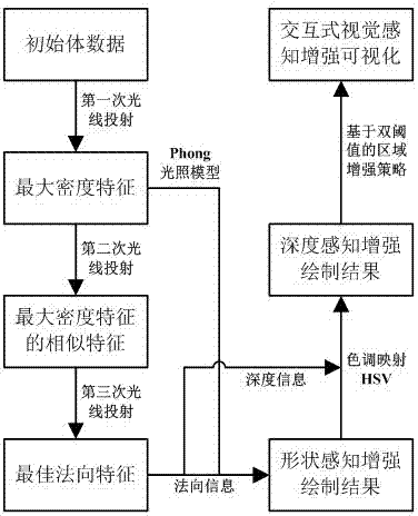
[0019] see figure 1 , the concrete steps of the inventive method are as follows:

[0020] Step 1): Read in the volume data, use the classic maximum density projection method (ie MIP algorithm), perform the first ray projection on the volume data to obtain the maximum density feature in the current line of sight direction; and the density of the maximum density feature The value is used as a color component, directly projected to the screen pixel corresponding to the current line of sight, and the depth information and density value information of the maximum density feature are recorded, and then the rendering result image of the maximum density projection method of the volume data is obtained. Taking the spatial position where the maximum density feature is located as the termination poin...


PUM


Abstract

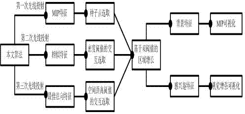
The invention discloses a maxim intensity projection method based on enhanced visual perception. The maxim intensity projection method based on the enhanced visual perception comprises the following steps: getting volume data of a target object, a first light projection of the volume data is conducted so that maxim intensity characteristics of a current line-of-sight direction is obtained and a drawing result image of the volume data is also obtained; taking the spatial position of the maxim intensity characteristics as an end, a second light projection of the volume data along the current line-of-sight direction is conducted, similar characteristics before the maxim intensity characteristics is obtained according to a similar threshold which is alternatively set by users and a drawing result image of the similar characteristics is obtained; taking the location of the similar characteristics as a start, a third light projection of the volume data along an opposite direction of the current line-of-sight is conducted, finding a sampling point which owns the maxim gradient model and taking the sampling point as the best normal characteristics of the maxim intensity characteristics, and obtaining a drawing result image of the best normal characteristics; and utilizing normal information of the best normal characteristics, a light treatment of the maxim intensity characteristics is conducted so that a shaping perception enhanced image of the maxim intensity characteristics is obtained.

Description

technical field [0001] The invention relates to a method for enhancing the visual perception of the rendering result of the maximum density projection method, and belongs to the technical field of volume data visualization and image processing. Background technique [0002] Direct Volume Rendering (DVR) is a classic algorithm in the field of scientific computing visualization research (Max N..Optical Models for Direct Volume Rendering[J].IEEE Transactions on Visualization and Computer Graphics,1995,1(2): 99–108), the optical properties (ie color, opacity) of the sampling point are defined by the transfer function (TF), and then the color value of the corresponding pixel in the two-dimensional image is obtained by accumulation. The resulting image drawn can reveal the hidden features in the volume data, which provides an effective means for users to understand and analyze the initial volume data. However, the drawing results of DVR are too dependent on the global classificat...

Claims


Application Information

Patent Timeline
IPC IPC(8): G06T15/08G06T15/06
Inventor 林海周志光
Owner ZHEJIANG UNIV
Learn More