
Vertical column type transformer

A transformer and column-type technology, applied in the field of column-type transformers, can solve the problems of inconvenient maintenance and use, affecting the appearance of the environment, and large floor space, and achieve the effects of simplifying the structure, beautifying the environment, and reducing the floor space

Inactive Publication Date: 2013-04-10
曾庆赣
View PDF4 Cites 3 Cited by
  • Summary
  • Abstract
  • Description
  • Claims
  • Application Information

AI Technical Summary

Problems solved by technology

[0002] In order to transmit electric energy to thousands of households, distribution transformers or prefabricated substations including distribution transformers must be widely used. These transformers or prefabricated substations generally occupy a large area and affect the appearance of the environment; especially overhead high-voltage lines At present, many three-phase distribution transformers on both sides of the street are installed on the platform bracket supported by the column, and the low-voltage switchgear is hung outside, which not only affects the appearance, but also occupies a large area and is inconvenient for maintenance and use.

Method used


Image

  • Vertical column type transformer
  • Vertical column type transformer
  • Vertical column type transformer

Examples


Embodiment Construction

[0022] Embodiments of the present invention are described in detail below, examples of which are shown in the drawings, in which the same or similar reference numerals denote the same or similar elements or elements having the same or similar functions. The embodiments described below by referring to the figures are exemplary only for explaining the present invention and should not be construed as limiting the present invention.

[0023] In the description of the present invention, the terms "first", "second", "third" and "fourth" are used for descriptive purposes only, and should not be understood as indicating or implying relative importance.

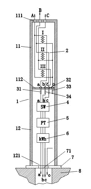
[0024] Such as figure 1 As shown, it is a column type transformer, which includes:

[0025] A column-shaped shell 1 is provided with a partition 112 inside the shell 1, thereby dividing the inside of the shell 1 into an upper installation area 11 and a lower installation area 12, and a high-voltage inlet port 111 is provided at the u...


PUM

PropertyMeasurementUnit
diameteraaaaaaaaaa
heightaaaaaaaaaa
diameteraaaaaaaaaa

Abstract

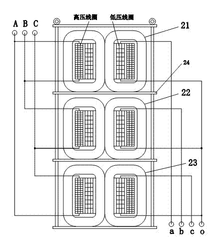
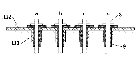
The invention relates to a vertical column type transformer. The vertical column type transformer is characterized by comprising a vertical column-shaped outer casing, a first conductive column, a second conductive column, a third conductive column, a fourth conductive column, a transformer body, an SW low-voltage switch, a PT protecting device, a kWh kilowatt-hour meter, and a fixing device, wherein the inside of the outer casing is provided with a separating plate to separate the inside of the outer casing into an upper mounting area and a lower mounting area, the first conductive column, the second conductive column, the third conductive column and the fourth conductive column are respectively arranged on the separating plate, the transformer body is arranged in the upper mounting area, low-voltage leads a, b, c and o of the transformer body are respectively and electrically connected with one ends of the first conductive column, the second conductive column, the third conductive column and the fourth conductive column, the SW low-voltage switch, the PT protecting device and the kWh kilowatt-hour meter are arranged in the lower mounting area and are sequentially connected in series, the input ends a, b and c of the SW low-voltage switch are respectively and electrically connected with the other end of the first conductive column, low-voltage leading-out wires a, b and c of the kWh kilowatt-hour meter and a low-voltage leading-out wire o of the transformer body are respectively connected with an external cable by low-voltage wire outlets, the fixing device is arranged at the lower end of the lower mounting area, and the fixing device is provided with wire outlets which are communicated with the low-voltage wire outlets. The vertical column type transformer has the advantages that the development toward high altitude is realized, the land occupation area is greatly reduced, the environment-beautifying effect is realized, the operation and the maintenance are convenient, and the like.

Description

technical field [0001] The invention relates to a column type transformer. Background technique [0002] In order to transmit electric energy to thousands of households, distribution transformers or prefabricated substations including distribution transformers must be widely used. These transformers or prefabricated substations generally occupy a large area and affect the appearance of the environment; especially overhead high-voltage lines At present, many three-phase distribution transformers on both sides of the street are installed on the platform bracket supported by the column, and the low-voltage switchgear is hung outside, which not only affects the appearance, but also occupies a large area and is inconvenient for maintenance and use. [0003] If the three-phase distribution transformer and its supporting switches and protective metering devices can be integrated with the supporting column, this column-shaped transformer or prefabricated substation will reduce the o...

Claims


Application Information

Patent Timeline
Patent Type & Authority Applications(China)
IPC IPC(8): H01F30/12H01F27/02H01F27/29H01F27/40H01F27/32H01F27/08H02B5/02
Inventor 曾庆赣
Owner 曾庆赣
Learn More