
Machining method of motor rotor magnetic steel ring of electric vehicle

A technology of motor rotor and processing method, which is applied in electric vehicles, motors, manufacturing stator/rotor body, etc., can solve the problems of narrowing the width of magnetic steel sheets, complex processing technology, and reducing material costs.

Inactive Publication Date: 2013-04-10
CHANGYING XINZHI TECH CO LTD
View PDF4 Cites 5 Cited by
  • Summary
  • Abstract
  • Description
  • Claims
  • Application Information

AI Technical Summary

Problems solved by technology

The inner wall of the magnetic steel ring can also be provided with bosses at intervals. The magnetic steel sheets are pasted in the inner groove formed between the bosses. The number of magnetic steel sheets remains unchanged. The presence of the bosses does not affect the Hall signal and performance of the motor. The width of the steel sheet is narrowed, thus reducing the material cost, and because of the integrated structure of the magnetic steel ring, the inner groove of the inner wall of the magnetic steel ring is usually formed by drawing and cutting operations with large-scale equipment, and the drawn-cut shaped inner groove With a curved surface, the magnetic steel sheet does not fit well with the curved surface
The processing accuracy of the one-piece magnetic steel ring is not easy to realize, and the processing technology is complicated, which leads to an increase in cost

Method used


Image

  • Machining method of motor rotor magnetic steel ring of electric vehicle
  • Machining method of motor rotor magnetic steel ring of electric vehicle
  • Machining method of motor rotor magnetic steel ring of electric vehicle

Examples


Embodiment Construction

[0024] The present invention will be further described below in conjunction with the drawings.

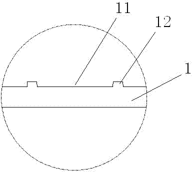
[0025] Such as Figure 1-3 As shown, the steel strip is punched into a steel plate punch 1 with an inner groove 11 after passing through the punching equipment. The inner grooves 11 are formed with a distance between the protrusions 12, and after a predetermined length is cut to form a single-layer steel plate punch . Use equipment to stack the multi-layer steel plate punching sheet 1 into a punching sheet block 2 of a predetermined height, such as Figure 4 Shown. The laminated punch block 2 is bent by an external force to form an annular cylindrical magnetic steel ring 3 through a mold, such as Figure 5-7 As shown, the cylindrical magnetic steel ring 3 that has been bent and formed is connected to form an integral structure by welding, riveting or self-fastening. Image 6 In the example in the example, welding is used for fixed connection.

[0026] Such as Figure 7-9 As shown, the...


PUM


Abstract

The invention discloses a machining method of a motor rotor magnetic steel ring of an electric vehicle. A punching disc is punched by steel plate strips after materials are obtained, wherein the punching disc is provided with a concave groove. The punching disc is cut into single-layer steel plate punching discs after the length of the punching disc is predetermined. A multi-layer steel plate punching disc is pressed into a punching disc block with predetermined height in an overlying mode through equipment. The annular cylindrical magnetic steel rings are formed by bending the punching disc block which is pressed in the overlying mode through external force. The cylindrical magnetic steel rings which are formed in a bending mode are connected into a whole in a welding mode or in a riveting mode or in a self-buckling mode.

Description

Technical field [0001] The invention relates to the field of electric vehicle motors, in particular to a method for processing a magnetic steel ring of an electric outer rotor assembly. Background technique [0002] The electric vehicle motor plays a vital role as the driving component of the vehicle, directly affecting the climbing ability and driving range of the electric vehicle. The electric vehicle motor includes a stator assembly and a rotor assembly. The rotor assembly includes a hub, a magnetic steel ring arranged inside the hub, and a magnetic steel sheet covering the inner wall of the magnetic steel ring. The magnetic steel ring is a one-piece structure, and the processing technology is complicated. The material in the middle of the magnetic steel ring becomes waste after being hollowed out. The material cost is very high; the magnetic steel sheet can be attached to the inner wall of the magnetic steel ring one by one. The inner wall surface is smooth. The inner wall ...

Claims


Application Information

Patent Timeline
Patent Type & Authority Applications(China)
IPC IPC(8): H02K15/03
CPCY02T10/64
Inventor 尹兴满
Owner CHANGYING XINZHI TECH CO LTD
Learn More