Photoelectric relay capable of discharging quickly

A photoelectric relay, a fast technology, applied in the electronic field, can solve the problem of slow discharge speed of photoelectric relays, and achieve the effects of increased current magnification, fast discharge speed, and accelerated charge extraction

Inactive Publication Date: 2013-04-10
UNIV OF ELECTRONICS SCI & TECH OF CHINA
View PDF3 Cites 11 Cited by
  • Summary
  • Abstract
  • Description
  • Claims
  • Application Information

AI Technical Summary

Problems solved by technology

[0007] The invention provides a fast-discharging photoelectric relay, which adopts double-stage or multi-stage triode cascade connection as a control circuit, and after cascading, the magnification factor increases, the circuit discharge capability is enhanced, and the power MOSFET turn-off speed is improved, which can solve the problem of traditional photoelectric relays. The discharge speed is slow and other problems

Method used


Image

  • Photoelectric relay capable of discharging quickly
  • Photoelectric relay capable of discharging quickly
  • Photoelectric relay capable of discharging quickly

Examples


Embodiment Construction

[0016] The present invention will be further described below in conjunction with accompanying drawing and embodiment, in the accompanying drawing:

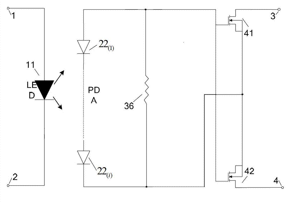
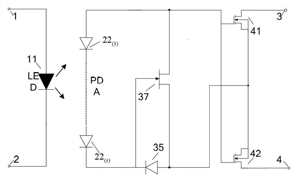
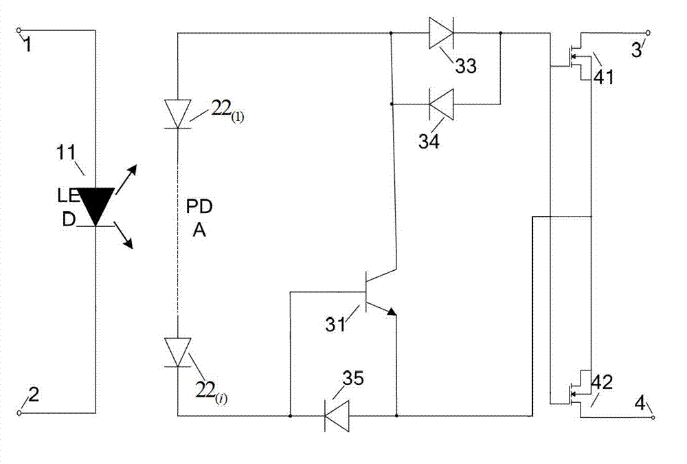
[0017] The circuit principle diagram of this patent sees figure 2 . The figure includes a pair of input terminals 1 and 2, and a pair of output terminals 3 and 4. It works as follows:

[0018] An external voltage is provided to the input circuit, and the voltage drops across the PN junction of the LED11, and the LED11 generates photons to emit light. The photodiode array 22 receives the light signal, generates a voltage by light, drives the circuit, and realizes the isolation control of the control circuit and the load circuit. According to different circuit performance requirements, changing the number of photodiode arrays can achieve the purpose of providing different voltages and ensure that the circuit can work reliably within the voltage range. The control circuit is two or more triodes cascaded. This patent takes two NPN...


PUM


Abstract

The invention discloses a photoelectric relay capable of discharging quickly, and belongs to the technical field of electronics. The photoelectric relay comprises an input end light-operated signal producing circuit, a light-operated signal receiving and photovoltaic conversing circuit, a control circuit and an output circuit. The input end light-operated signal producing circuit is composed of a light-emitting diode (LED) (11). The light-operated signal receiving and photovoltaic conversing circuit is composed of a photodiode array (PDA). The control circuit comprises a cascade audion and three diodes, and is used for providing a charge-discharge channel for power metal oxide semiconductor field effect transistor (MOSFET) components of the output circuit. The output circuit comprises a pair of power MOSFET components. According to the photoelectric relay capable of discharging quickly, cascade of two or a plurality of audions is adopted in the control circuit, current amplification times of the audions are amplified after cascade, and speed of extracting charges is accelerated obviously. Compared with an existing photoelectric relay, the photoelectric relay capable of discharging quickly is faster in discharging speed and can be applied to relay situations of higher frequency.

Description

technical field [0001] The invention belongs to the field of electronic technology and relates to a photoelectric relay. Background technique [0002] The photoelectric relay is an electronic control device, which uses a photoelectric isolation device to isolate the control terminal from the load terminal. The working principle of the photoelectric relay is to convert the optical signal of the light-emitting diode (LED) into an electrical signal through the photodiode array PDA (Photo Diode Array), and control the conduction of the output stage power MOSFET (MetalOxide Semiconductor Field Effect Transistor) through the control circuit. On and off to drive the load. The output circuit of the photoelectric relay is usually composed of a power MOSFET, and the load is driven by turning on and off the MOSFET. But in order to reset the relay, the gate electrode of the power MOSFET needs to discharge the charge as soon as possible. Therefore, various built-in control circuits ha...

Claims


Application Information

Patent Timeline
Patent Type & Authority Applications(China)
IPC IPC(8): H03K17/78H03K17/567
Inventor 乔明许琬蔡林希李燕妃吴浩然张昕吴文杰张有润张波
Owner UNIV OF ELECTRONICS SCI & TECH OF CHINA
Why Eureka
Try Eureka