Resource distribution method and base station of distributed antenna system

A distributed antenna and resource allocation technology, applied in the field of communication, can solve problems such as increasing system throughput

Active Publication Date: 2013-04-10
ZTE CORP
View PDF3 Cites 13 Cited by
  • Summary
  • Abstract
  • Description
  • Claims
  • Application Information

AI Technical Summary

Problems solved by technology

[0004] The technical problem to be solved by the present invention is to provide a resource allocation method and a base station in a distributed antenna system, so as to solve the problem of realizing load balancing between sectors without increasing additional signaling overhead and terminal complexity. thereby increasing the overall throughput of the system

Method used


Image

  • Resource distribution method and base station of distributed antenna system
  • Resource distribution method and base station of distributed antenna system
  • Resource distribution method and base station of distributed antenna system

Examples


Embodiment 1

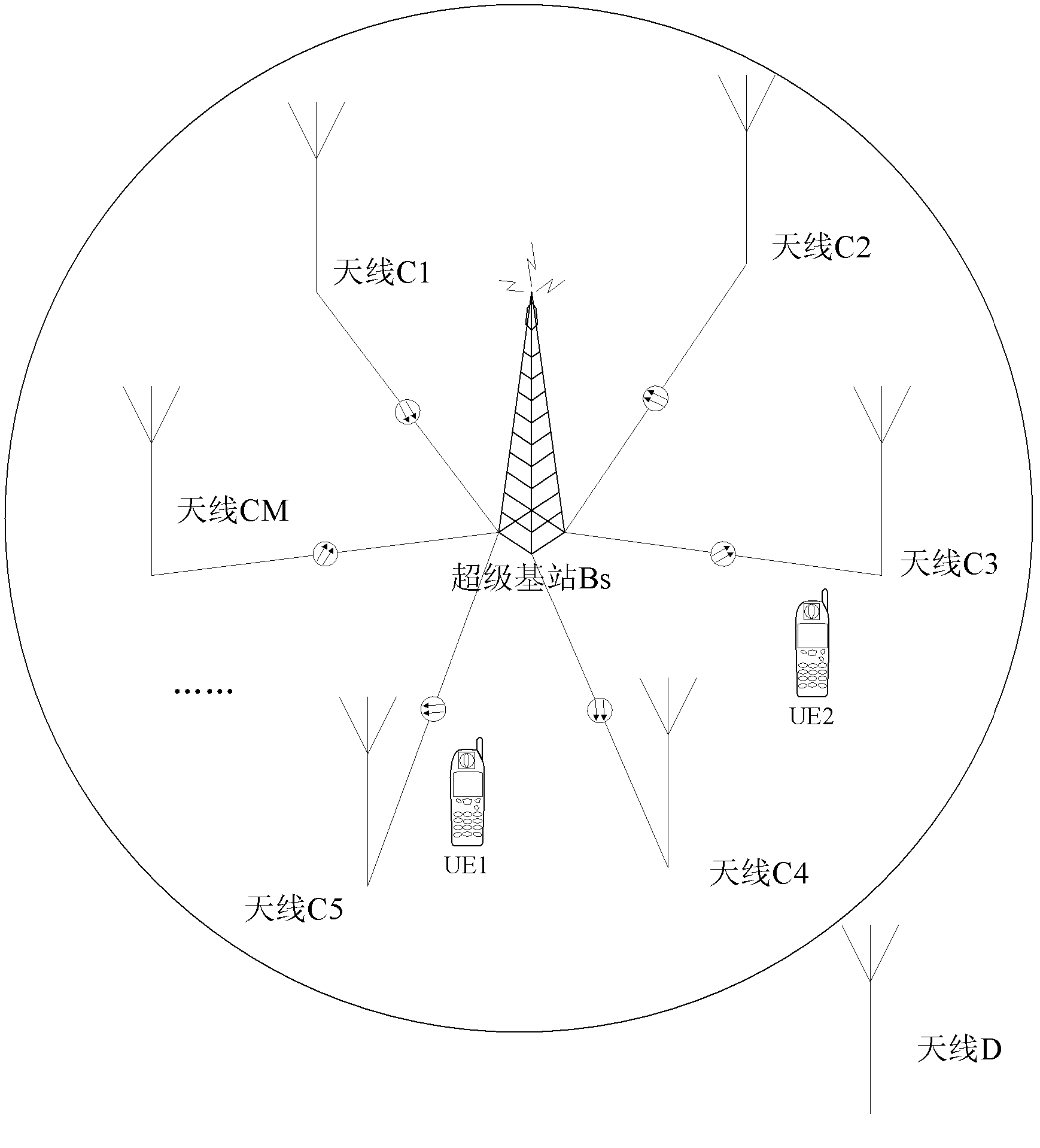
[0090] Suppose in a distributed antenna system, such as image 3 As shown, there is a super base station, denoted as Bs, with M antenna stations, antennas C1, C2...CM are connected to the super base station through optical fibers, so it can be said that the sectors represented by these antenna terminals belong to the super base station Bs, and the antennas The sector represented by D does not belong to the super base station Bs, and the sector to which each antenna station belongs is recorded as a set C, C={C1, C2...CM}, and the system configures thresholds R, L1, L2, assuming that there is one Terminal U, whose serving sector is CS, belongs to set C, then the communication process between terminal U and base station Bs is as follows: Figure 4 shown, including the following steps:

[0091] Step S101, the terminal U periodically reports measurement information;

[0092] Wherein, the measurement information includes the measurement information from the terminal U to the servi...

Embodiment 2

[0107] Assume that in a distributed antenna system, there is a super base station, denoted as Bs, with M antenna stations, and the sector to which each antenna station belongs is denoted as set C, C = {C1, C2, ..., CM} , the system configures thresholds R, L1, and L2. Suppose there is a terminal U whose serving sector is CS and belongs to set C. The communication process between terminal U and base station Bs includes the following steps:

[0108] Step S201, the super base station periodically counts the load of all sectors in the sector set C, and finds out the index set T of all sectors whose load is less than a given threshold L2, T={T1, T2,...TP} ;

[0109] Among them, the calculation method of the load is:

[0110] Load = (the number of resource blocks that have been allocated + the number of resource blocks that have not been allocated but need to be allocated) / the total number of resource blocks.

[0111] Step S202, the terminal U periodically reports measurement info...

Embodiment 3

[0130] Assume that in a distributed antenna system, there is a super base station, denoted as Bs, with M antenna stations, and the sector to which each antenna station belongs is denoted as set C, C={C1, C2...CM}, the system Configure the thresholds R, a, and b. Assume that there is a terminal U whose serving sector is CS and belongs to the set C. The communication process between the terminal U and the base station Bs includes the following steps:

[0131] Step S301, the super base station periodically counts the loads of all sectors in the sector set C, and calculates the thresholds L2, L1, and finds out the index set T of all sectors whose loads are less than the threshold L2, T={T1, T2, ...TP};

[0132] Among them, the calculation method of the load is:

[0133] Load = (the number of resource blocks that have been allocated + the number of resource blocks that have not been allocated but need to be allocated) / the total number of resource blocks.

[0134] The calculation ...


PUM


Abstract

The invention provides a resource distribution method and a base station of a distributed antenna system. The resource distribution method and the base station of the distributed antenna system comprises that whether a measured value of metrical information reported by a base station detecting terminal from a terminal to a service section is bigger than a first threshold value. Whether capacity of the service section is higher than a second threshold value. If a detected measured value of the metrical information reported by the base station detecting terminal from the terminal to the service section is bigger than the first threshold value, and accordingly the capacity of the service section is higher than the second threshold value, a resource artificial switching operation of the base station detecting terminal is carried out. The resource distribution method and the base station of the distributed antenna system can solve the problem that load balancing among the sections can be achieved under the premise of increasing no additional signaling overheads and complexity of the terminal, and therefore total handling capacity of the distributed antenna system is increased.

Description

technical field [0001] The present invention relates to the communication field, in particular to a method for scheduling and allocating resources in a distributed antenna system and a base station. Background technique [0002] The distributed antenna system is a new type of network architecture, which is also called Coordinative Multiple Point (COMP) transmission in the LTE-A (Long term evaluation-Advanced, advanced long-term evolution) system. In the architecture, the baseband units of several adjacent base stations are concentrated in a super base station to form a centralized BBU (Base Band Unit, baseband unit). The intermediate frequency or radio frequency signal generated by the BBU passes through the RoF (Radio over Fiber, optical load The wireless communication) optical fiber is transmitted to each wireless remote unit (Radio Remote Unit, RRU for short), that is, the antenna station. The antenna stations in the distributed antenna system can be regarded as multiple...

Claims


Application Information

Patent Timeline
Patent Type & Authority Applications(China)
IPC IPC(8): H04W72/08H04W72/12
Inventor 罗薇刘锟鲁照华李卫敏
Owner ZTE CORP
Why Eureka
Try Eureka