Stepless speed change system and method for rotor wing of twin-engine helicopter

A helicopter rotor, continuously variable speed technology, applied in mechanical equipment, gear transmission, belts/chains/gears, etc., can solve the problems of uneven transition of rotation speed, uneven loading of planetary gears, and bulky speed change system, and achieves a solution to the problem. The effect of planetary gear equalization, stable shifting process and high system integration

Pending Publication Date: 2021-03-26
NO 60 RES INST OF GENERAL STAFF DEPT PLA
View PDF7 Cites 2 Cited by
  • Summary
  • Abstract
  • Description
  • Claims
  • Application Information

AI Technical Summary

Problems solved by technology

[0003] The speed change systems disclosed in the above two patents are both conventional cylindrical gear planetary transmissions, and the power input shaft and output shaft of the speed change parts are arranged in parallel, which is inconsistent with the transmission layout of horizontal input and vertical output required by general helicopters, and additional The corresponding reversing transmission device makes the entire transmission system bulky
[0004] In addition, due to the use of conventional cylindrical gear planetary transmission, it is necessary to process a larger-sized fixed ring gear. The fixed ring gear deforms greatly during processing and heat treatment, resulting in uneven loads in the actual use of the planetary gear, thus Cause the partial load of the transmission system, affect the transmission efficiency and transmission life, and even affect the flight safety
[0005] Most of the current helicopter transmission systems are step-variable, especially two-stage variable speed, so the helicopter can only choose a relatively good speed between the two speed stages, which has certain limitations
In addition, the stepped transmission system is likely to cause shock loads during the speed change process, resulting in an unstable transition of the speed and affecting flight safety.

Method used


Image

  • Stepless speed change system and method for rotor wing of twin-engine helicopter
  • Stepless speed change system and method for rotor wing of twin-engine helicopter
  • Stepless speed change system and method for rotor wing of twin-engine helicopter

Examples


Embodiment Construction

[0019] The present invention will be further introduced below in conjunction with the accompanying drawings and specific embodiments.

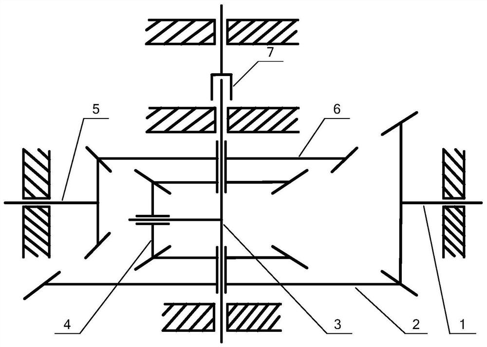
[0020] to combine Figure 1-Figure 3 , a kind of continuously variable speed system for twin-engine helicopter rotors in this embodiment consists of a right drive gear 1, a lower double gear 2, a planetary carrier 3, a planetary gear 4, a left drive gear 5, an upper double gear 6, and an overrunning The clutch 7 is composed; the above-mentioned gears are bevel gears (straight bevel gears or spiral bevel gears can be used);

[0021] The upper duplex gear 6 and the lower duplex gear 2 are coaxially arranged, and both are supported on the planet carrier 3 through bearings;

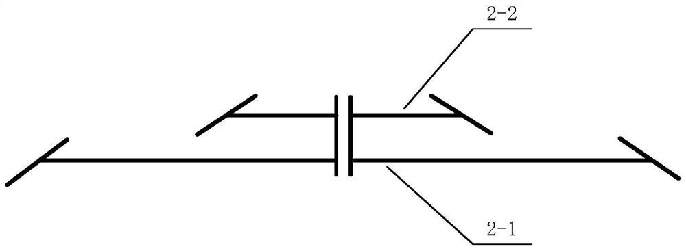
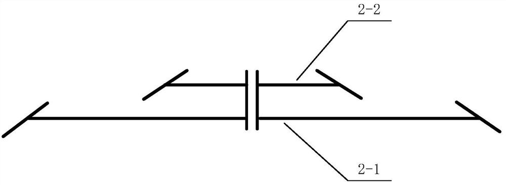
[0022] The right drive gear 1 is used as one of the horizontal power input terminals, which meshes with the lower bevel gear 2-1 of the lower double gear 2, and the upper bevel gear 2-2 of the lower double gear 2 meshes with the planetary gear 4, so The planetary gear 4 mes...


PUM


Abstract

The invention discloses a stepless speed change system and method for a rotor wing of a twin-engine helicopter. The system comprises a right driving gear, a lower duplicate gear, a planet carrier, a planet gear, a left driving gear, an upper duplicate gear and an overrunning clutch. The gears are all bevel gears. The upper duplicate gear and the lower duplicate gear are coaxially arranged and aresupported on the planet carrier through bearings. The right driving gear serves as one horizontal power input end and is meshed with a lower bevel gear of the lower duplicate gear, an upper bevel gearof the lower duplicate gear is meshed with the planet gear, the planet gear is meshed with a lower bevel gear of the upper duplicate gear, an upper bevel gear of the upper duplicate gear is meshed with the left driving gear, and the left driving gear serves as the other horizontal power input end. A rotating shaft of the planet gear is connected with the planet carrier. The rotating axis of the planet carrier is in the vertical direction, the upper end of the planet carrier serves as an output end, and the rotor wing is driven through the overrunning clutch. According to the method, the stepless speed change requirement of the planet carrier can be met by adjusting the rotating speeds of the left driving gear and the right driving gear.

Description

technical field [0001] The invention belongs to the field of helicopter rotor transmission, in particular to a continuously variable speed change system and method for twin-engine helicopter rotors. Background technique [0002] The optimal speed of the rotor of the helicopter is different under different flight conditions. In order to reduce the fuel consumption of the helicopter and improve the endurance of the helicopter, the transmission system is generally required to have the ability to change speed. Most of the existing transmission systems use spur gear planetary gears for transmission. For example, CN201410066639.X (a variable speed transmission system for drones) discloses a two-stage transmission system, which is arranged in a conventional cylindrical gear planetary transmission system through control. The on-off of the friction clutch and the brake in the vehicle cooperates to achieve the purpose of changing the transmission route, and then realizes the switching...

Claims


Application Information

Patent Timeline
Patent Type & Authority Applications(China)
IPC IPC(8): F16H3/76
CPCF16H3/76
Inventor 杨红图杨长盛高鹏宋武生
Owner NO 60 RES INST OF GENERAL STAFF DEPT PLA
Why Eureka
Try Eureka