Synchronous belt-worm gear and its transmission

A technology of synchronous pulley and synchronous belt, which is applied in the direction of transmission, belt/chain/gear, mechanical equipment, etc., can solve the problems of large occupied space and complex structure, achieve convenient use and maintenance, simplify the transmission chain, and be easy to bend Effect

Active Publication Date: 2016-04-20
SUZHOU UNIV
View PDF5 Cites 0 Cited by
  • Summary
  • Abstract
  • Description
  • Claims
  • Application Information

AI Technical Summary

Problems solved by technology

[0005] The technical problem to be solved by the present invention is: to overcome the shortcomings of complex structure and large occupied space in the prior art when worm drive and synchronous belt drive are used in series, and to provide a simple structure, compact size, easy to manufacture and maintain Convenient transmission parts and its transmission mechanism, which directly convert the rotation of the worm into the low-speed motion of the synchronous belt in the plane of the worm axis or the low-speed rotation of the synchronous pulley arranged at a staggered angle of 90 degrees to the worm

Method used


Image

  • Synchronous belt-worm gear and its transmission
  • Synchronous belt-worm gear and its transmission
  • Synchronous belt-worm gear and its transmission

Examples


Embodiment 1

[0021] The tooth surface of the synchronous belt-worm gear provided by the present invention is composed of the tooth surface of the worm gear and the tooth surface of the synchronous belt wheel. The manufacturing process of cutting the tooth surface of the synchronous pulley and then cutting the tooth surface of the worm gear is feasible. For the convenience of the statement, the manufacturing process of first cutting the tooth surface of the synchronous pulley and then cutting the tooth surface of the worm gear is used as an example to illustrate.

[0022] See attached figure 1 And attached figure 2 , the specific implementation of the synchronous belt-worm gear provided in this example is as follows: In order to avoid the manufacture of special hobs, reduce manufacturing costs and ensure transmission quality, the pitch P b A synchronous pulley slightly greater than or equal to the standard worm shaft pitch mπ, the pitch circle diameter D of this synchronous pulley is slig...

Embodiment 2

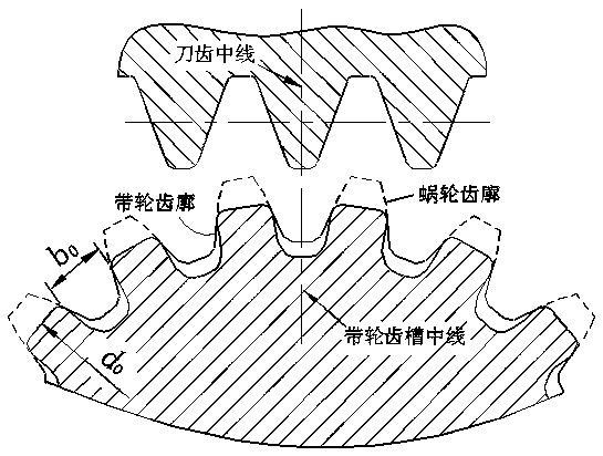
[0039] The method of cutting the synchronous belt-worm gear is similar to the above-mentioned embodiment 1, the only difference is that during radial feeding, the hob tooth centerline does not coincide with the tooth groove centerline of the synchronous pulley, so that the cut worm wheel tooth groove centerline Relative to the synchronous pulley cogging center line, a slight angle δ is deviated as in formula (7):

[0040] (7)

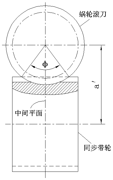
[0041] In formula (7), πm is the lead of the single-head hob, D 0 is the diameter of the outer cylinder of the synchronous belt, φ is the central angle of the overlapping part of the hob addendum circle and the outer circle of the synchronous pulley, see the attached figure 1 .

[0042] The above deflection angle δ should be just so that the hob teeth will not cut into the tooth surface of one side of the synchronous pulley, and at the same time, the depth of cutting into the tooth surface of the other side of the synchronous pulley is the minimum, s...

Embodiment 3

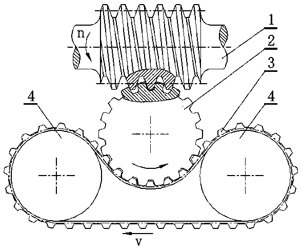
[0044] This embodiment provides a worm-synchronous belt transmission device, which mainly includes a worm, a synchronous belt-worm wheel, a synchronous belt with outer teeth and several pulleys; the synchronous belt-worm wheel is provided by Embodiment 1. See attached image 3 , the structure of the worm-synchronous belt transmission device is: the synchronous belt-worm wheel 2 meshes with the worm 1; Arranged so that the timing belt close to the worm goes around and meshes with the timing belt-worm wheel. The device directly transforms the rotation of the driving worm into the low-speed motion of the synchronous belt in the plane of the worm axis through the synchronous belt-worm gear.


PUM


Abstract

The invention relates to a synchronous belt-worm gear and a transmission device thereof. The synchronous belt-worm gear is a cylindrical gear-shaped part. The gear tooth face of the synchronous belt-worm gear consists of a worm gear tooth face and a synchronous pulley tooth face, wherein the worm gear tooth face can be meshed with a worm, and the synchronous pulley tooth face can be meshed with a synchronous belt. The synchronous belt-worm gear comprises two structures, wherein one of the two structures is that all tooth faces respectively comprise part of the worm gear tooth face and part of the synchronous pulley tooth face, and the other structure is that one side tooth face of gear teeth is the complete synchronous pulley tooth face, and one part of the other side tooth face of the gear teeth is the worm gear tooth face, and the other part of the other side tooth face of the gear teeth is the synchronous pulley tooth face. Through the transmission device formed by the synchronous belt-worm gear, the synchronous belt-worm gear is meshed with the worm to obtain movement and power, and the synchronous belt-worm gear is meshed with the synchronous belt to transmit the movement and the power to the synchronous belt. The transmission device provided by the invention has the characteristics that the structure is simple, and manufacturing is convenient. The rotation of the active worm can be converted into the low-velocity movement of the synchronous belt in the axial plane of the worm, or the low-velocity rotation of the synchronous pulley in a compact space, wherein the synchronous pulley and the worm are arranged at an axial alternate angle of 90 degrees.

Description

technical field [0001] The invention relates to a mechanical transmission part and its application, in particular to a worm wheel part and its transmission mechanism. Background technique [0002] Worm gear transmissions are used to transmit motion and power between two spatially staggered axes, usually at a staggered angle of 90 degrees. Since the worm gear teeth are continuous helical teeth, they can continuously mesh with the worm gear teeth, without the process of entering and exiting meshing, so the transmission of the worm gear is stable and the noise is very low; and because the number of worm teeth is small (only one gear teeth), so the worm gear transmission can obtain a large transmission ratio with a compact structure; in addition, because the worm gear teeth are hobbed by the worm gear hob that is exactly the same shape as the worm gear, although the worm gear and the worm gear are arranged in a staggered axis , but the line contact and meshing transmission can ...

Claims


Application Information

Patent Timeline
Patent Type & Authority Patents(China)
IPC IPC(8): F16H37/12
CPCF16H37/12
Inventor 钱志良
Owner SUZHOU UNIV
Why Eureka
Try Eureka