
Centrifugal compressor

A centrifugal compressor and impeller technology, applied in mechanical equipment, non-variable pumps, machines/engines, etc., can solve the problem that the compression process cannot always maintain a saturated state, the compressor inlet and compressor outlet cannot be guaranteed, and the compression performance is safe Poor reliability and other problems, to achieve the effect of convenient oil supply pipeline, high degree of automation, and low compression cost

Inactive Publication Date: 2013-04-17
溧阳德维透平机械有限公司
View PDF7 Cites 9 Cited by
  • Summary
  • Abstract
  • Description
  • Claims
  • Application Information

AI Technical Summary

Problems solved by technology

The above prior art cannot guarantee that the compressor inlet, the interior of the compressor and / or the compressor outlet are always in a saturated state, that is, the compressor cannot always maintain a saturated state during the compression process of water vapor
Therefore, the existing compressors have the problems of low compression efficiency and high compression cost, resulting in waste of energy
At the same time, the existing compressors also have problems such as poor compression performance, poor safety and reliability, and short service life.

Method used


Image

  • Centrifugal compressor
  • Centrifugal compressor
  • Centrifugal compressor

Examples


Embodiment

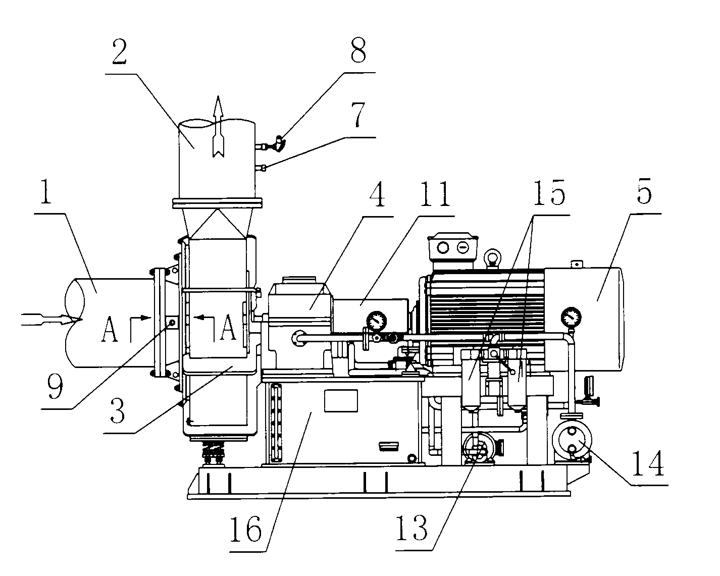
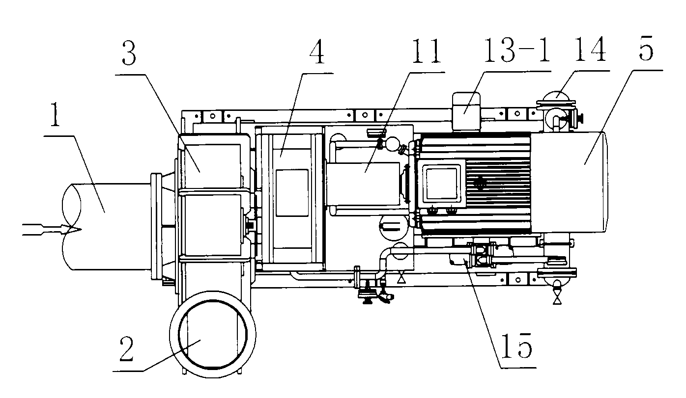
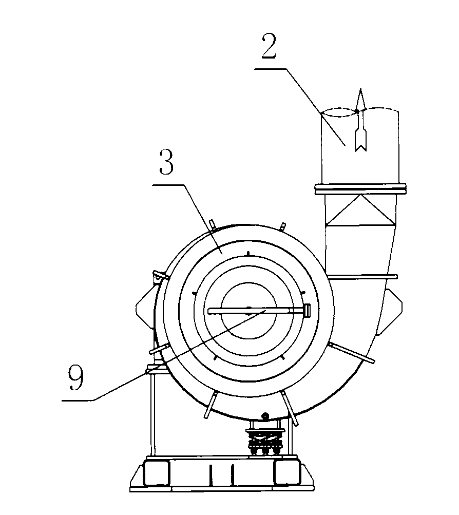
[0033] like Figure 1 ~ Figure 3 as well as Figure 5 As shown, a centrifugal compressor includes a volute 3 connected to the inlet pipe 1 and the outlet pipe 2, and also includes an impeller 10 and a motor 5, and the impeller 10 is placed in the volute 3, as known in the prior art : The motor 5 can be directly connected with the impeller 10, that is, the power output end of the motor 5 is connected with the impeller 10.

[0034] In order to improve the compression efficiency of the compressor, the following technical measures are taken: the water spray pipe 9 containing the shower head 901 is added, the water spray pipe 9 is arranged on the air inlet pipe 1, or the water spray pipe 9 is arranged on the volute 3, and the water spray The nozzle 901 of the pipe 9 faces the inner cavity of the volute 3 , that is, the nozzle 901 faces the impeller 10 .

[0035] In this way, the water spray pipe 9 sprays water into the volute 3 through the spray nozzle 901, so as to ensure that t...


PUM


Abstract

The invention relates to a compressor, in particular to a centrifugal compressor. The centrifugal compressor is mainly applicable to compression of steam and comprises a volute (3) connected with a steam inlet pipe (1) and a steam outlet pipe (2), an impeller (10) and a motor (5). The impeller (10) is arranged in the volute (3), and a power output end of the motor (5) is connected with the impeller (10). The centrifugal compressor is further provided with a water spraying pipe (9) comprising a sprayer (901), the water spraying pipe (9) is arranged on the steam inlet pipe (1), or the water spraying pipe (9) is arranged on the volute (3), and the water spraying pipe (901) faces an inner cavity of the volute (3). By means of the technical scheme, the compression efficiency is high, compression cost is low, performance is stable, reliability is good, and service life is long. The centrifugal compressor achieves automatic control of the pressure and temperature.

Description

technical field [0001] The invention relates to a compressor, in particular to a centrifugal compressor. The present invention is mainly applicable to the compression of water vapor. The invention belongs to the technical field of equipment manufacturing and processing. Background technique [0002] Centrifugal compressor is a general-purpose machine that increases gas pressure and is used in many sectors of the national economy. For example, the centrifugal compressor is used as a new heat recycling device, which not only reduces the evaporation temperature, improves the quality of the product, but also reduces energy demand, and at the same time realizes the circular economic operation of energy and materials. [0003] Chinese patent announcement number CN201335030Y discloses a centrifugal compressor, which mainly includes an impeller and a motor, the motor is directly connected to the impeller, and the motor is controlled by a frequency converter; the impeller is a thr...

Claims


Application Information

Patent Timeline
IPC IPC(8): F04D29/58F04D29/063
Inventor 罗春龙王正全
Owner 溧阳德维透平机械有限公司
Learn More