Dynamic stress monitoring device of propeller main shaft

A dynamic stress and monitoring device technology, which is applied in the direction of measuring devices, force/torque/work measuring instruments, mechanical parts testing, etc., to achieve the effect of convenient installation

Inactive Publication Date: 2015-02-04
NO 719 RES INST CHINA SHIPBUILDING IND
View PDF6 Cites 0 Cited by
  • Summary
  • Abstract
  • Description
  • Claims
  • Application Information

AI Technical Summary

Problems solved by technology

There are two technical bottlenecks in realizing the dynamic stress monitoring of the rotating shaft in the liquid: first, how to convert the rotating signal into a non-rotating signal; second, the transmission of the signal in the liquid

Method used


Image

  • Dynamic stress monitoring device of propeller main shaft
  • Dynamic stress monitoring device of propeller main shaft

Examples


Embodiment Construction

[0020] The present invention will be further described below in conjunction with accompanying drawing.

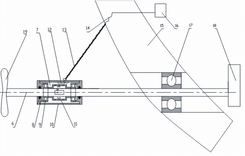
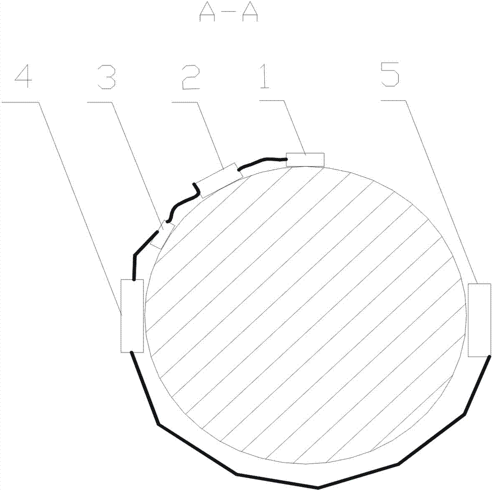
[0021] Such as figure 1 , 2 As shown, the dynamic stress monitoring device for the propeller main shaft includes a strain measurement circuit, two bearings 9, and a bearing seat 10. The two bearings 9 are set on the propeller main shaft 6, and the bearing 9 is installed on the bearing seat 10. The bearing seat 10 Bearing caps 8 are arranged on both sides of the shaft, and the two ends of the propeller main shaft 6 and the bearing seat 10 are sealed with a contact seal structure to ensure that the bearing cap 8, the bearing 9, the bearing seat 10, and the propeller main shaft 6 form a closed cavity together. The bearing block 10 is fixedly connected with the hull 15 through a fixed chain lock 13, and a strain gauge 1, a bridge box 2, a digital-to-analog converter 3, a transmitter 4, and a power supply 5 are pasted on the propeller main shaft located in the closed cavity. T...


PUM


Abstract

The invention discloses a dynamic stress monitoring device of a propeller main shaft. The dynamic stress monitoring device comprises a bearing seat, a bearing and a strain measuring circuit, wherein the bearing is sleeved on the propeller main shaft, the bearing is arranged on the bearing seat, the propeller main shaft is connected with two ends of the bearing seat in a sealing way so as to form a sealing cavity between the inner wall of the bearing seat and the periphery of the propeller main shaft, the propeller main shaft is provided with a strain gauge, a DAC (Digital-to-Analog converter), a transmitter and a power supply, the strain measuring circuit is formed by electrically connecting the strain gauge, the DAC, the transmitter and the power supply, and the inner wall of the bearing seat is provided with a receiving antenna which is used for receiving a signal transmitted by the transmitter and transmitting the received signal to a data collection processing system on a ship body. According to the dynamic stress monitoring device disclosed by the invention, a dynamic stress variation rule of the propeller main shaft can be obtained in real time, and essential basis is provided for the design of a propeller, the propeller main shaft and a propeller bearing.

Description

technical field [0001] The invention relates to a dynamic stress monitoring device for a propeller main shaft. Background technique [0002] Ship navigation mainly depends on the thrust of the propeller, and the propeller is mostly a cantilever structure. Due to the propeller's own gravity and the difference in pressure difference between the upper and lower parts of the propeller, the main shaft of the cantilever propeller has a large deflection deformation. In complex sea conditions, this deflection and deformation lead to complex alternating loads on the propeller shaft, which act on the propeller bearings and cause damage to the propeller bearings. [0003] Therefore, if the dynamic stress change law of the propeller main shaft can be obtained, it can provide a basic basis for the design of propellers, propeller main shafts, propeller bearings, etc. However, there are two technical bottlenecks in realizing the dynamic stress monitoring of the rotating shaft in the liqu...

Claims


Application Information

Patent Timeline
Patent Type & Authority Patents(China)
IPC IPC(8): G01L5/12G01M13/00
Inventor 杨俊王隽张金国张雪冰姚世卫赵广
Owner NO 719 RES INST CHINA SHIPBUILDING IND
Why Eureka
Try Eureka