Energy light wave transmitting system

A transmission system, light wave technology, used in electric vehicles, electrical components, transportation and packaging, etc., can solve problems such as user confusion, user hooking, and accidents.

Inactive Publication Date: 2013-04-17
邱金和
View PDF6 Cites 2 Cited by
  • Summary
  • Abstract
  • Description
  • Claims
  • Application Information

AI Technical Summary

Problems solved by technology

[0002] Electronic devices have changed the way of life of most people in the world, especially portable electronic devices are necessary equipment for everyone, such as Personal Digital Assistant (Personal Digital Assistant, PDA), satellite navigation device (Global Positioning System) ), laptops (notebooks) or mobile phones (mobile phones), etc., if vehicles are considered to be so-called electric vehicles, the common feature of these products is that they must use electricity to drive them, and they are generally charged during charging. In the process, a power line is used to insert the electronic device or electric vehicle into each other to form electrical conduction, so that it can charge the battery or storage device, but if these products are to be charged at the same time, it must be pulled Multiple power cords are used for charging. If the distance is far away, an extension cord must be used for charging. Those who walk may accidentally get hooked and cause accidents.
On the other hand, some people will rely on the alarm clock function of the mobile phone to control the time to wake up. If the mobile phone is out of power and there is no socket near the bed, it will definitely cause trouble for the user.

Method used


Image

  • Energy light wave transmitting system
  • Energy light wave transmitting system
  • Energy light wave transmitting system

Examples


Embodiment Construction

[0025] In order to achieve the above-mentioned purpose and effect, the technical means and structure adopted by the present invention are now illustrated in detail with respect to the preferred embodiments of the present invention. Its features and functions are as follows for complete understanding.

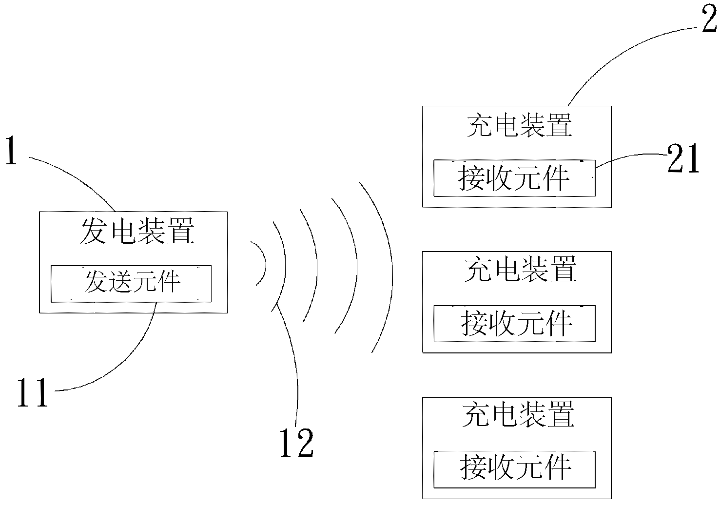
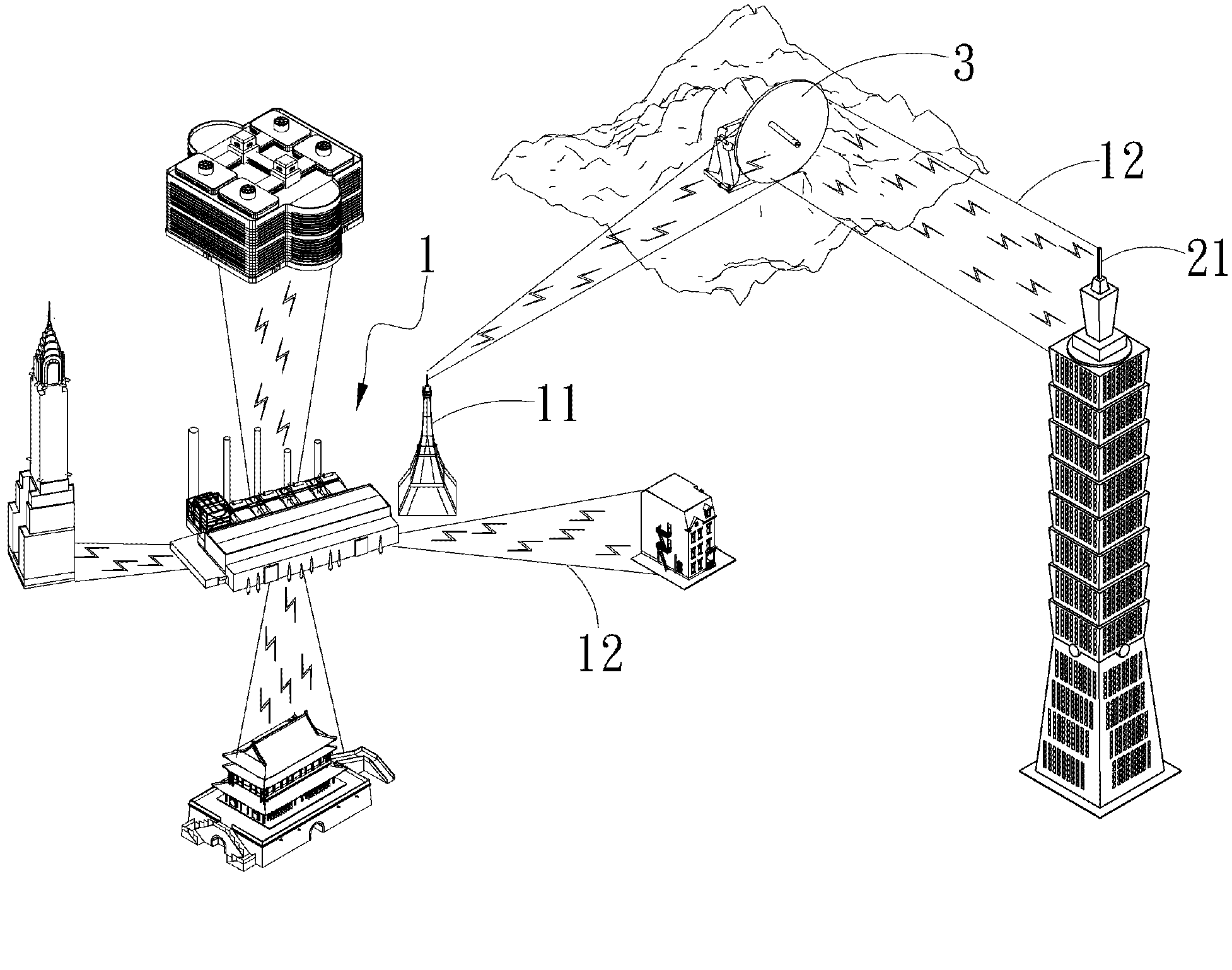
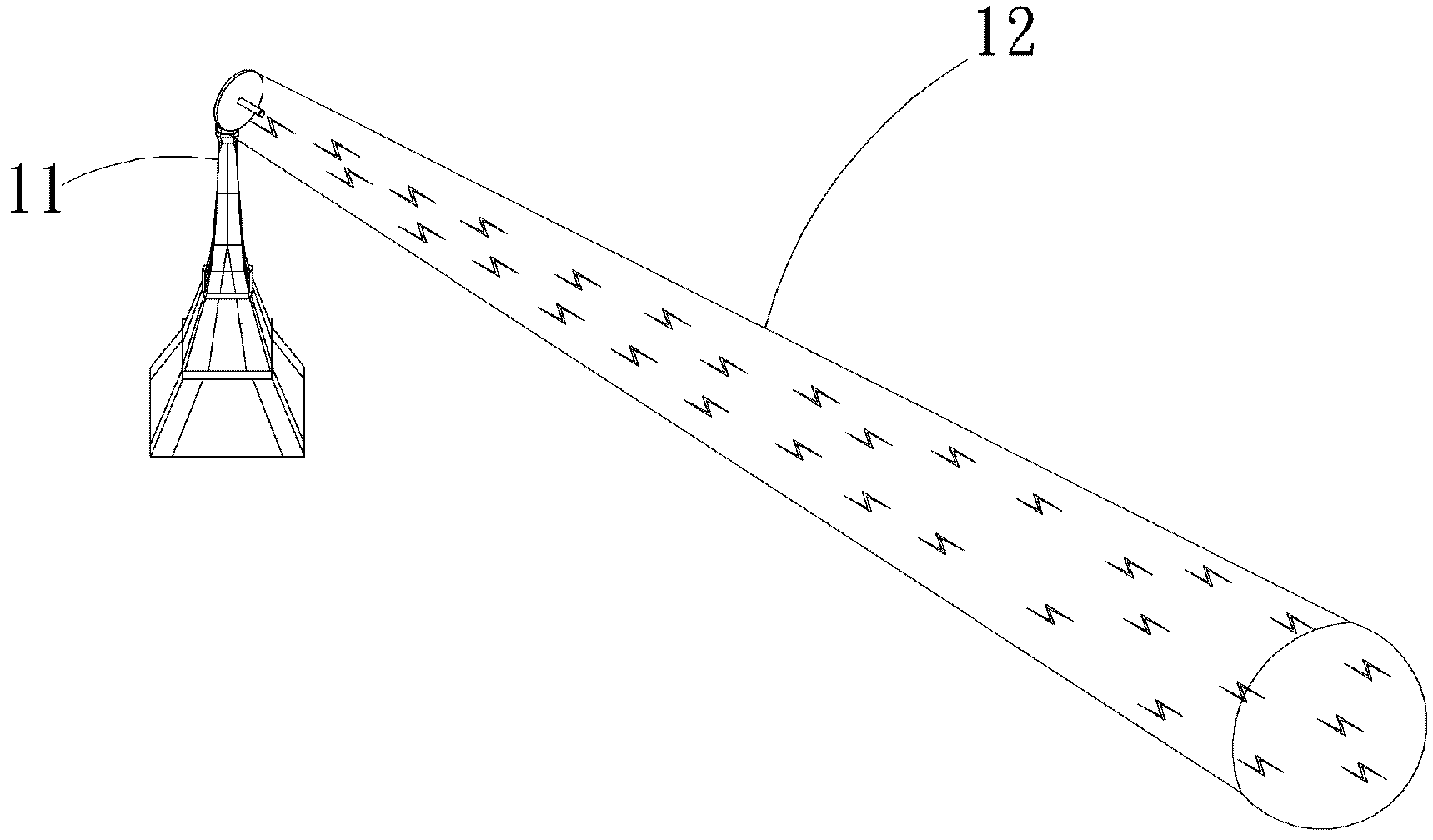
[0026] see figure 1 , figure 2 and image 3 Shown, be the schematic block diagram of preferred embodiment of the present invention, implementation schematic diagram and one, can find out clearly that the present invention mainly comprises from the figure:

[0027] A power generating device 1, the power generating device 1 can be driven by an electric power source, and at least one transmitting element 11 is arranged in the generating device 1, and the transmitting element 11 can emit a light wave 12 with a power source, and the light wave 12 The power source is wrapped in a wrapping method to prevent the power source from leaking between transmissions;

[0028] At least one ...


PUM


Abstract

The invention relates to an energy light wave transmitting system which is mainly characterized in that a transmitting element in a power generation device transmits light waves with a power source, a receiving element in at least one charging device receives the light waves, and the light waves are applied to the charge or electricity storage of an electronic device. In addition, when the charging device is not within an illuminating range of the light waves, the light waves transmitted by the transmitting element are received by a switching device and are transmitted to the charging device of a remote end. Therefore, the advancement that a power source can be transmitted to the remote end can be achieved without any line.

Description

technical field [0001] The invention relates to a light wave transmission system, in particular to an energy light wave transmission system in which a power source is contained in the light wave. Background technique [0002] Electronic devices have changed the way of life of most people in the world, especially portable electronic devices are necessary equipment for everyone, such as Personal Digital Assistant (PDA), Satellite Navigator (Global Positioning System) ), laptops (notebooks) or mobile phones (mobile phones), etc., if vehicles are considered to be so-called electric vehicles, the common feature of these products is that they must use electricity to drive them, and they are generally charged during charging. In the process, a power cord is used to insert the electronic device or electric vehicle into each other to form electrical conduction, so that it can charge the battery or storage device, but if these products are to be charged at the same time, it must be pu...

Claims


Application Information

Patent Timeline
IPC IPC(8): H02J7/02H02J50/30
Inventor 邱金和
Owner 邱金和
Why Eureka
Try Eureka