Serial-magnetic-circuit hybrid-excitation permanent magnet motor

A hybrid excitation, permanent magnet motor technology, applied in the direction of magnetic circuit static parts, magnetic circuit rotating parts, synchronous motors with static armatures and rotating magnets, etc., can solve the problem of reducing motor power density and low material utilization. , complex motor structure and other problems, to achieve the effect of low distortion rate, high power density, and overcoming adjustment difficulties

Inactive Publication Date: 2013-04-17
南京维特力源自动化控制有限公司
View PDF3 Cites 12 Cited by
  • Summary
  • Abstract
  • Description
  • Claims
  • Application Information

AI Technical Summary

Problems solved by technology

Among these hybrid excitation permanent magnet motors, some hybrid excitation permanent magnet motors coexist in radial and axial magnetic circuits, thus increasing the length of the motor magnetic circuit, making the axial length of the motor not too long
The rotor of some hybrid excitation permanent magnet motors is divided into two sections, and the two sections of rotors are independent of each other on the magnetic circuit. It can be regarded as a combination of a permanent magnet synchronous motor and an electric excitation synchronous motor, so the utilization rate of materials is low, which reduces the motor. power density
Some hybrid excitation permanent magnet motors have an additional air gap, which reduces the efficiency of the motor and complicates the motor structure

Method used


Image

  • Serial-magnetic-circuit hybrid-excitation permanent magnet motor
  • Serial-magnetic-circuit hybrid-excitation permanent magnet motor
  • Serial-magnetic-circuit hybrid-excitation permanent magnet motor

Examples


Embodiment Construction

[0022] The present invention will be described in further detail below in conjunction with the accompanying drawings and specific embodiments.

[0023] Example.

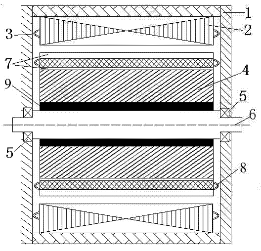
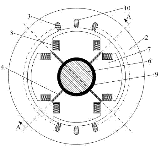
[0024] Depend on figure 1 , 2 It can be seen that the series magnetic circuit hybrid excitation permanent magnet motor of the present invention includes a casing 1, and a stator core 2 is arranged in the casing 1. The stator core 2 is slotted 10 along the circumferential direction, and the stator winding 3 is arranged in the slot 10. The casing 1 and the stator core 2 are fixed. A rotating shaft 6 is disposed inside the casing 1 , and the rotating shaft 6 is connected to the casing 1 through a bearing 5 . A rotor core 7 and a rotor non-magnetic material 9 are disposed on the rotating shaft 6 , and a permanent magnet 4 and a rotor excitation winding 8 are disposed on the rotor core 7 . The permanent magnet 4 , the rotor core 7 , the rotor excitation winding 8 and the rotor non-magnetic material 9 can rotate togeth...


PUM


Abstract

The invention relates to a serial-magnetic-circuit hybrid-excitation permanent magnet motor, which comprises a case. A stator consisting of stator core and a stator winding, and a rotor consisting of a permanent magnet, a rotating shaft, a rotor core, an excitation winding and a nonmagnetic material are installed in the case. The stator winding is distributed in a slot which is circumferentially arranged in the stator core. The permanent magnet and the excitation winding are arranged on the rotor core. Magnetic motive force sources established by the permanent magnet and the excitation winding are connected in series in the form of magnetic circuits. The nonmagnetic material is arranged between the rotor core and the rotating shaft. By adjusting the current of the excitation winding, the air-gap magnetic field of a motor can be conveniently adjusted. The excitation winding is only used for realizing the auxiliary adjustment of the air-gap magnetic field and the effect of the permanent magnet is fully exerted; the main magnetic field adjusting capacity is better; the structure of the serial-magnetic-circuit hybrid-excitation permanent magnet motor is similar to the structure of a common synchronous motor, the power density is higher, and the optimization design of the motor winding and the magnetic pole shape is facilitated to obtain sinusoidal voltage waveform; and an additional air gap and an axial magnetic circuit do not exist.

Description

technical field [0001] The invention belongs to the field of motors and relates to a permanent magnet motor. Background technique [0002] Permanent magnet motors have many advantages such as high efficiency, high power density, and flexible structure. This makes permanent magnet motors widely used in fields such as oil fields, mines, steel mills, textiles, and aerospace. However, the permanent magnet motor has the disadvantage of difficulty in adjusting the air gap magnetic field. When the permanent magnet motor is used as a generator, its terminal voltage will change with the load size, load nature or prime mover speed and other factors, thus affecting the quality of power supply; When the permanent magnet motor is used as a motor, it is difficult to obtain a wide range of speed regulation. Therefore, the disadvantage of difficult adjustment of the air-gap magnetic field of permanent magnet motors limits the wide application and promotion of permanent magnet motors to a ...

Claims


Application Information

Patent Timeline
Patent Type & Authority Applications(China)
IPC IPC(8): H02K21/12H02K21/04H02K1/17H02K1/27
Inventor 夏永洪黄劭刚张景明陈瑛
Owner 南京维特力源自动化控制有限公司
Why Eureka
Try Eureka