Power generator forced excitation control method under condition of power system faults

A technology of power system and control method, which is applied in the direction of controlling generators, control systems, electrical components, etc., and can solve problems such as unfavorable system stability, limited improvement effect of system stability, unfavorable system transient stability, etc.

Inactive Publication Date: 2013-04-17
ZHEJIANG UNIV
View PDF3 Cites 4 Cited by
  • Summary
  • Abstract
  • Description
  • Claims
  • Application Information

AI Technical Summary

Problems solved by technology

Forced excitation unit, forced excitation control amount, forced excitation start and exit time are the main factors affecting the effect of forced excitation control. Incentive control may be detrimental to system stability
[0006] Bayne J P et al. proposed in the literature titled Static exacter control to improve transient stability (IEEE Trans on Power System, 1975, PAS-94(4): 1141-1146) that the start-up logic of generator strong excitation is generally the generator terminal voltage The sudden drop exceeds a certain limit and the generator speed deviation also exceeds a certain limit; when using this forced excitation logic, on the one hand, only the units near the short-circuit point can obviously feel the impact of the fault and start the forced excitation control. The strong excitation control is usually not activated when the disturbance is small. Since there are fewer units actually participating in the forced excitation control during the fault period, the improvement effect on system stabilit...

Method used


Image

  • Power generator forced excitation control method under condition of power system faults
  • Power generator forced excitation control method under condition of power system faults
  • Power generator forced excitation control method under condition of power system faults

Examples


Embodiment Construction

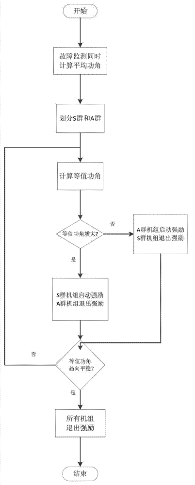
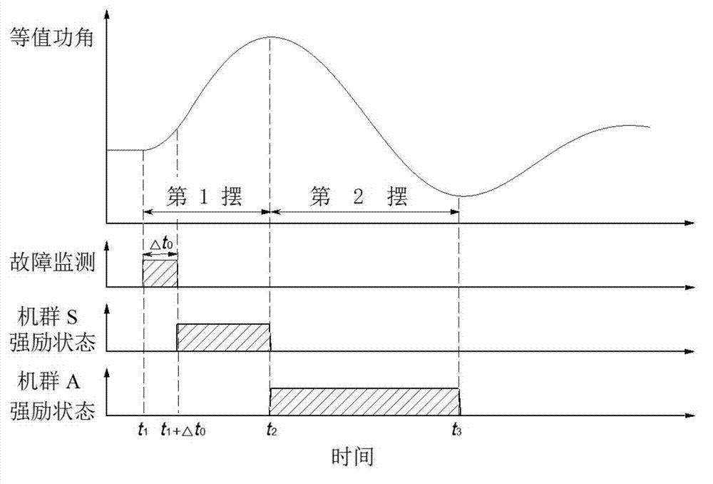
[0039] In order to describe the present invention more specifically, the generator strong excitation control method of the present invention will be described in detail below in conjunction with the accompanying drawings and specific embodiments.

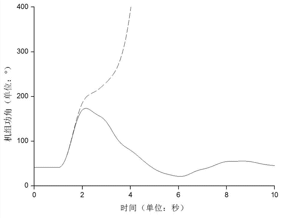
[0040] The following takes the Southern Power Grid system as an example. The Southern Power Grid is mainly composed of power grids in Yunnan, Guizhou, Guangxi, Guangdong, and Hainan. Hainan Power Grid is relatively small and independent due to its geographical location. According to the simulation calculation data used in the example, there are 253 generator sets in Guangdong Power Grid with a total installed capacity of 121558MVA; there are 123 generator sets in Guangxi Power Grid with a total installed capacity of 36468MVA; There are 170 generator sets with a total installed capacity of 45267MVA.

[0041] First of all, the generators in the power system that meet the following two conditions at the same time are classified as the ...


PUM


Abstract

The invention discloses a power generator forced excitation control method under the condition of power system has faults, and the method comprises the following steps that power generators with large installed capacity and high excitation response are selected from a power system, and forced excitation controllers are arranged to the power generators; and when the working system has faults, all power generators in the system are classified into an S cluster and an A cluster according to the power-angle information of the power generators which is measured in a phase measuring unit in a wide area measuring system, and equivalent power angles of the whole system are calculated. The forced excitation startup/exit moments of all power generator units are determined by integrating the clusters that the power generators are located in according to the change rules of the equivalent power angles. According to the power generator forced excitation control method under the condition of the power system faults, the power generator forced excitation is started/shut up in a gradual swing mode according to the swinging frequency of a transient stable process of the system, so that enough forced excitation control force is applied to key swinging frequency on the one hand and partial power generator forced excitation does not over-brake the follow-up swinging frequency of the system on the other hand, and the role of the power generator forced excitation control in improving the transient stability of the system can be fully displayed.

Description

technical field [0001] The invention belongs to the technical field of power system control, and in particular relates to a generator forced excitation control method in the case of a power system failure. Background technique [0002] The power system is a unified whole composed of generators, transformers, converters, power lines and various electrical equipment that produce, transform, transmit, distribute and consume electric energy. The ability of each synchronous motor to maintain synchronous operation and transition to a new or return to the original steady-state operation mode after a large disturbance in the case of a power system fault is called the transient stability of the power system by the industry. [0003] Generator excitation control is an effective measure to improve the transient stability of the power system; when a short-circuit fault occurs in the AC system, the generator terminal voltage drops, the output electromagnetic power decreases, and the inpu...

Claims


Application Information

Patent Timeline
IPC IPC(8): H02P9/10
Inventor 徐政周煜智黄弘扬刘昇刘高任董桓锋
Owner ZHEJIANG UNIV
Why Eureka
Try Eureka