Motion compensation-based 1/4 pixel precision video image deinterlacing method

A technology of pixel precision and motion compensation, which is applied in the field of image processing, can solve the problems of poor deinterlacing processing effect of interlaced video images, inability to accurately obtain motion vectors, insufficient search accuracy, etc., to achieve appropriate and reduce computational complexity , Improve the effect of search accuracy

Inactive Publication Date: 2013-04-17
XIDIAN UNIV
View PDF5 Cites 12 Cited by
  • Summary
  • Abstract
  • Description
  • Claims
  • Application Information

AI Technical Summary

Problems solved by technology

Among them, the motion estimation adopts the whole-pixel block matching fast motion estimation method, and the motion compensation adopts the two-way motion compensation method. The disadvantage of this method is that the motion vector displacement within the search range of the whole-pixel motion estimation is at the whole-pixel level, If the object in the video sequence has fractional pixel-level motion, the existing integer-pixel motion estimation search accuracy is insufficient, and the motion vector of the real motion cannot be accurately obtained, and the relatively optimal matching block can only be found within the integer-pixel-level search range, resulting in Obvious blocking effect, poor effect on deinterlacing of interlaced video images

Method used


Image

  • Motion compensation-based 1/4 pixel precision video image deinterlacing method
  • Motion compensation-based 1/4 pixel precision video image deinterlacing method
  • Motion compensation-based 1/4 pixel precision video image deinterlacing method

Examples


Embodiment Construction

[0029] The present invention will be described in further detail below in conjunction with the accompanying drawings.

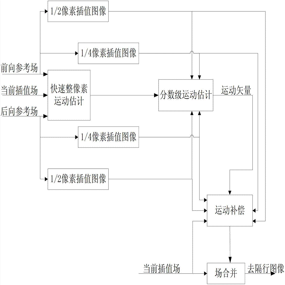
[0030] refer to figure 1 , the implementation steps of the present invention are as follows:

[0031] Step 1, select interpolation field and reference field:

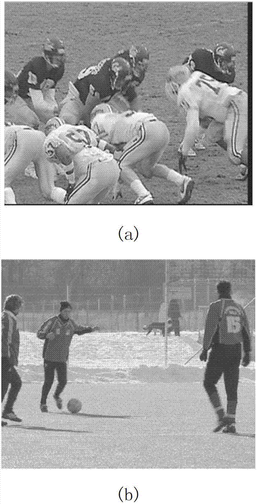
[0032] Read in an actual interlaced video sequence of 100 fields in raw format with a size of 352×288. The interpolation fields are selected sequentially from the start field to the end field in time order. After one field is selected as the interpolation field, two reference fields are selected respectively. The forward and backward fields of the interpolated field.

[0033] In step 2, half pixels are generated between the integer pixels of the forward and backward reference fields.

[0034] According to the difference between the half pixel point to be interpolated and the adjacent integer pixel point, apply different pixel point interpolation to obtain the half pixel point, and the implementation...


PUM


Abstract

The invention discloses a motion compensation-based 1 / 4 pixel precision video image deinterlacing method, to mainly solve the problem that the motion estimation precision in the conventional motion compensation deinterlacing method is limited. The method comprises the following steps of: reading an interlacing video sequence; selecting a corresponding interpolation field and a reference field; applying a sixth order limited impact response filter to carry out semi-pixel interpolation in the reference field; applying a complete pixel point and a semi-pixel point to a 1 / 4 pixel point of the reference field so as to carry out linear interpolation; applying an effective three-step searching method E3SS to carry out motion estimation on the complete pixel and the sub-pixel of the reference field; searching for a motion vector with the minimum absolute error and SAD; carrying out bidirectional motion estimation on the reference field so as to obtain two motion vectors; taking one with the minimum absolute error and SAD as the motion vector of a present block; and utilizing a corresponding reference block to carry out motion compensation according to the motion vector of the present block so as to obtain a deinterlacing image. According to the method, on the premise that the calculation complexity is not increased, the image quality is improved, and therefore the method can be used for deinterlacing of video images.

Description

technical field [0001] The invention belongs to the technical field of image processing, relates to the conversion of video image from interlaced scanning format to progressive scanning format, can be used for deinterlacing processing from interlaced scanning image to progressive scanning image, and is one of the research hotspots of video image deinterlacing in recent years. Background technique [0002] With the development of various new display devices and new TV broadcast formats, there are a large number of different format standards in the video field. In order to realize the exchange between video signals of different formats, video format conversion is indispensable. In today's TV broadcasting systems, most video signal sources use interlacing, which can reduce bandwidth requirements, but can cause crawling, flickering, blurred edges, and jagged edges. De-interlacing technology is a key technology of format conversion and the basis of other format conversion techno...

Claims


Application Information

Patent Timeline
Patent Type & Authority Applications(China)
IPC IPC(8): H04N7/01
Inventor 吴家骥焦李成孙晨艳白静马文萍马晶晶
Owner XIDIAN UNIV
Why Eureka
Try Eureka