
Client, access point, communication system and switching method

An access point switching and communication system technology, which is applied in the field of access points, clients, communication systems and switching, can solve the problems of difficult to accurately determine the RSSI threshold, difficult for the access point to determine the RSSI threshold, and the signal strength drops sharply.

Inactive Publication Date: 2013-04-17
SIEMENS AG
View PDF5 Cites 9 Cited by
  • Summary
  • Abstract
  • Description
  • Claims
  • Application Information

AI Technical Summary

Problems solved by technology

The determination of the place to start switching depends on the determination of the RSSI threshold, but the propagation process of wireless signals, that is, electromagnetic waves, is affected by various environmental factors around. In fact, it is difficult to determine an accurate RSSI threshold for each access point
[0007] From this it can be seen that in figure 2 In the illustrated embodiment, since the client's forward antenna i The signal strength of the signal received by the rear-facing antenna will drop sharply. It is necessary to ensure that the client has enough time to receive the signal from the AP. i Switch to AP i+1 , you need to accurately determine the RSSI threshold to accurately determine where to start switching, but the RSSI threshold is difficult to accurately determine
Once the determined RSSI threshold is inappropriate, the client cannot i Switch to AP i+1 on, the reliability of switching cannot be guaranteed
In addition, the switching quality is not high and the system cost is high

Method used


Image

  • Client, access point, communication system and switching method
  • Client, access point, communication system and switching method
  • Client, access point, communication system and switching method

Examples


Embodiment Construction

[0089] In order to make the object, technical solution and advantages of the present invention clearer, the present invention will be further described in detail below with reference to the accompanying drawings and examples.

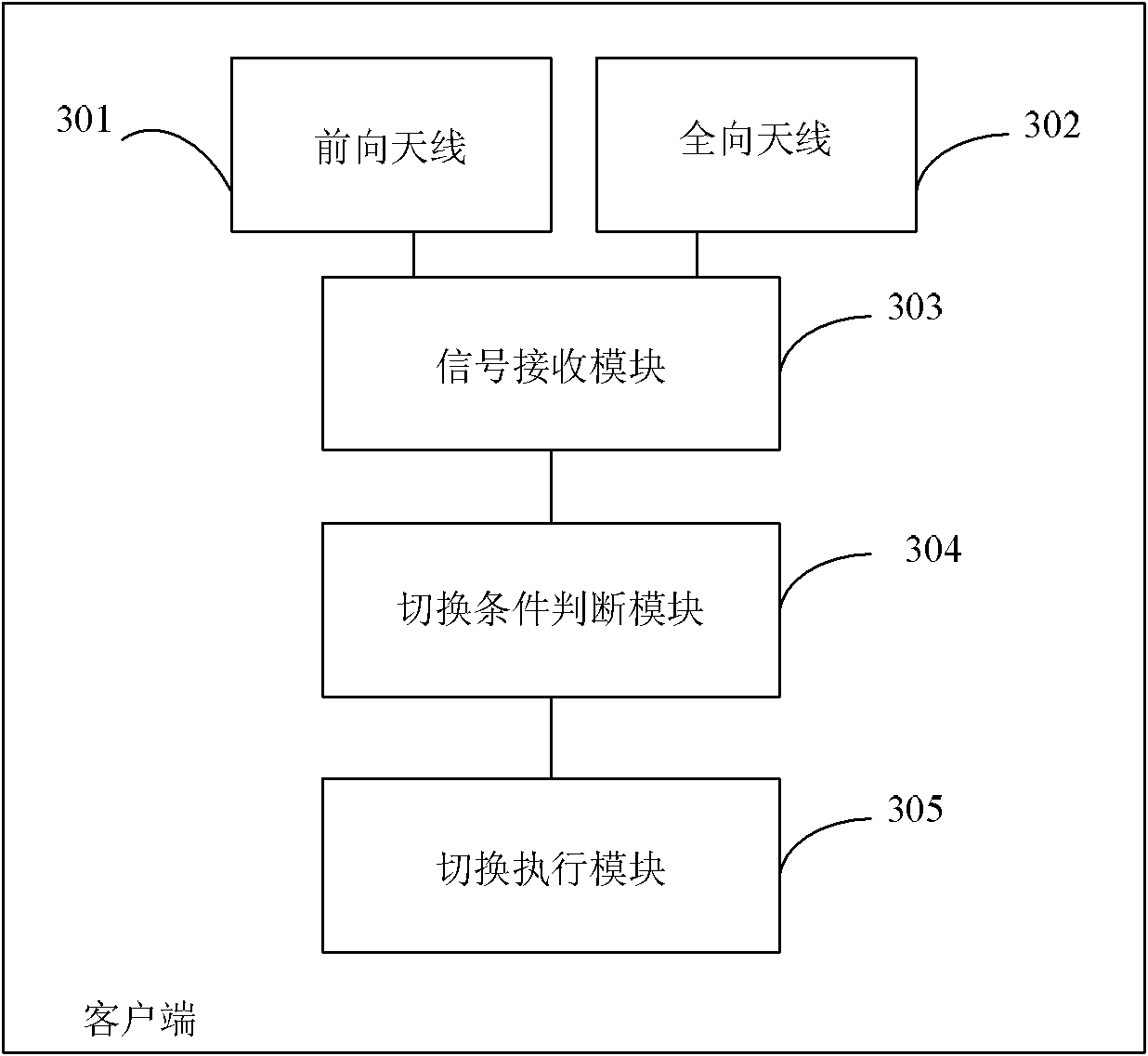
[0090] image 3 It is a schematic diagram of the first preferred structure of the client in the embodiment of the present invention. As shown in the figure, the client includes: a forward antenna 301 , an omnidirectional antenna 302 , a signal receiving module 303 , a handover condition judging module 304 and a handover execution module 305 .

[0091] Wherein, the signal receiving module 303 is configured to receive a signal of the first access point through the forward antenna 301 . When the client moves in a direction that first approaches the first access point and then approaches the second access point, and is within the common coverage of the first access point and the second access point, the signal receiving module 303 further It is used for r...


PUM


Abstract

The embodiment of the invention provides a client, an access point, a communication system and a switching method. When the client moves close to a first access point and then close to the second access point and is located in a commonly coverage range of the first and second access points, a signal receiving module is used for receiving signals from the first and second access points through an omnidirectional antenna. A switching condition judging module judges whether the switching condition is met or not according to the signal strength of the signal received at the first access point or the signal strength of signals received at the first and second access points. If so, a switching command is sent to a switch executing module. The switch executing module is used for starting a switching program to switch the client from the first access point to the second access point according to the switch executing command. The client, the access point, the communication system and the switching method ensure the switching reliability.

Description

technical field [0001] The present invention relates to wireless communication technology, in particular to a client, an access point, a communication system and a switching method. Background technique [0002] Due to the advantages of wireless communication-based subway control and passenger information systems, such as continuous two-way connection, high data transmission rate, and low cost, the system is attracting more and more attention nowadays. Taking the wireless subway communication system based on wireless local area network (WLAN) as an example, some access points (APs) are arranged along the railway track, and a client is set at the train end. The client on the train and the equipment beside the track can exchange information. [0003] figure 1 It is a schematic structural diagram of a wireless local network including a switching mechanism in the prior art. Such as figure 1 As shown, access points AP are set up along the subway track from left to right i-1 ...

Claims


Application Information

Patent Timeline
IPC IPC(8): H04W36/08H04W36/30
CPCH04B7/08H04W36/083H04W36/302H04W36/30
Inventor 张洁蓝培
Owner SIEMENS AG
Learn More