Intelligent cloud monitoring system of lightning arrester

A monitoring system and lightning arrester technology, applied in transmission systems, information technology support systems, instruments, etc., can solve the problems of unsafe reference voltage, easy to be affected by moisture and aging, and low waterproof level, so as to avoid data instability and not easy to be affected by moisture and aging , high waterproof effect

Pending Publication Date: 2018-05-18
宿迁电力设计院有限公司 +3
View PDF0 Cites 6 Cited by
  • Summary
  • Abstract
  • Description
  • Claims
  • Application Information

AI Technical Summary

Problems solved by technology

[0005] Many surge arresters online monitoring only monitor the full current data, and do not monitor the resistive current; compared with the full current, the resistive current can better reflect the health status of the arrester, and can give early warning of the deterioration of the arrester;
[0006] 2. The power supply of the online monitoring device is unstable:
[0007] Most of the existing on-line monitoring devices for lightning arresters use outdoor maintenance power as the power supply. The maintenance power is easily disturbed by objective factors, and accidental power failures and power outages cause the on-line monitoring devices to stop operating;
[0008] 3. The leakage current sensor is unstable:
[0009] Leakage current sensors are installed outdoors and have a low waterproof level. After a period of operation, they are prone to moisture and aging, resulting in unstable data and even sensor burnout;
[0010] 4. The acquisition of the reference voltage causes new unsafe hazards:
[0011] Most of the existing lightning arrester online monitoring uses PT secondary voltage as the reference voltage. The instability of the online monitoring device and cumbersome construction may cause a short circuit of the PT secondary voltage, which brings hidden dangers to the safe operation of the substation.

Method used


Image

  • Intelligent cloud monitoring system of lightning arrester
  • Intelligent cloud monitoring system of lightning arrester

Examples


Embodiment Construction

[0033] The following will clearly and completely describe the technical solutions in the embodiments of the present invention with reference to the accompanying drawings in the embodiments of the present invention. Obviously, the described embodiments are only some, not all, embodiments of the present invention. Based on the embodiments of the present invention, all other embodiments obtained by persons of ordinary skill in the art without making creative efforts belong to the protection scope of the present invention.

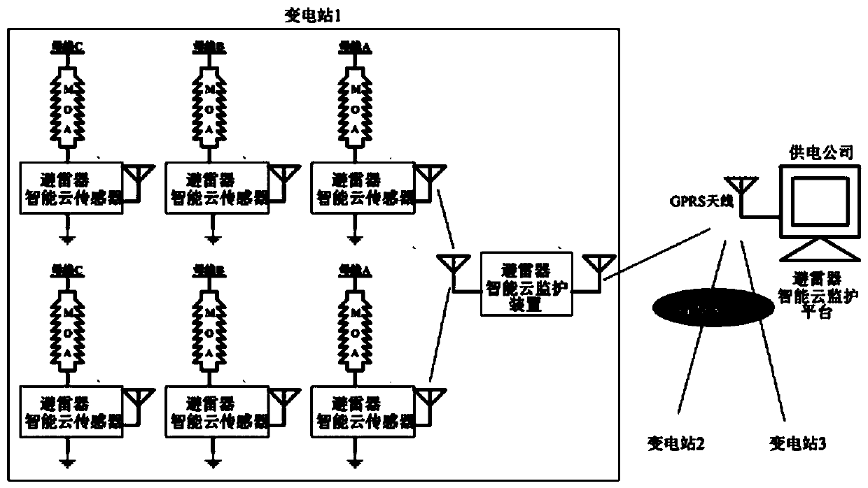
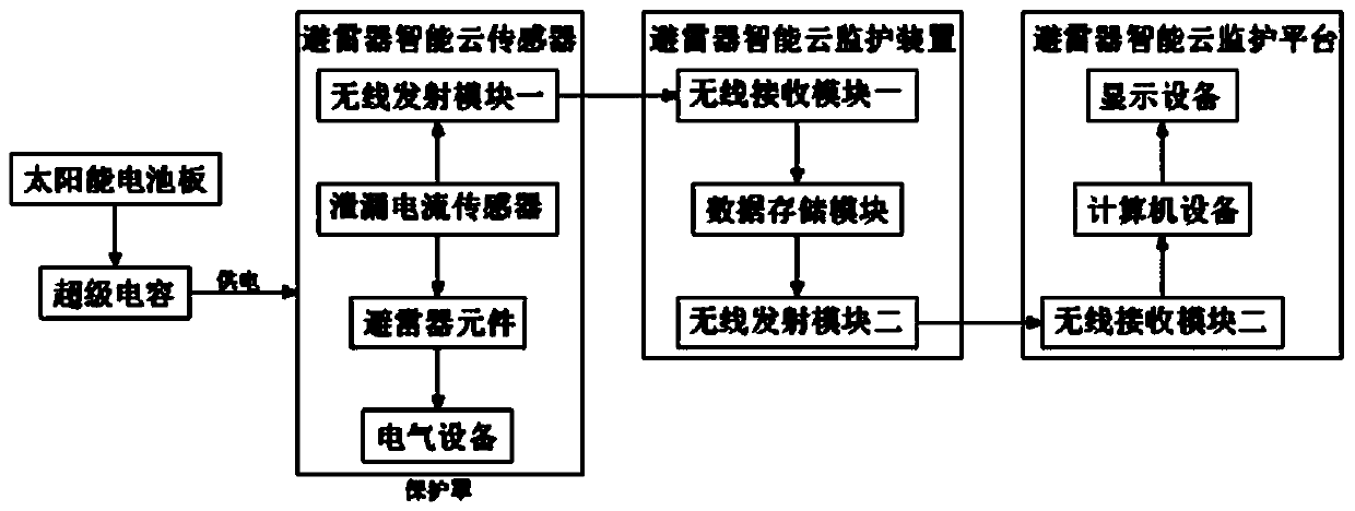
[0034] see Figure 1-2 , in an embodiment of the present invention, a lightning arrester intelligent cloud monitoring system includes a lightning arrester intelligent cloud sensor, a lightning arrester intelligent cloud monitoring device, and a lightning arrester intelligent cloud monitoring platform, and one lightning arrester intelligent cloud sensor is installed on each phase bus of a substation, The lightning arrester intelligent cloud sensor transmits rea...


PUM


Abstract

The invention relates to a power equipment monitoring system, in particular to an intelligent cloud monitoring system of a lightning arrester. The system comprises intelligent cloud sensors of the lightning arrester, an intelligent cloud monitoring device of the lightning arrester and an intelligent cloud monitoring platform of the lightning arrester; the intelligent cloud sensors of the lightningarrester are linked with the intelligent cloud monitoring device of the lightning arrester through a wireless network; the intelligent cloud sensors of the lightning arrester are arranged on all phases of buses of transformer substations and transmit real-time data to the intelligent cloud monitoring device of the lightning arrester through the wireless network. The system can not only display all pieces of data and curves of the lightning arrester in real time but also conduct cloud diagnosis, intelligent judgment and expert analysis on collected big data, maintenance personnel can understand the physical conditions of the lightning arrester conveniently, and power equipment is endowed with new capabilities and vitality, so that a power grid is stronger and more intelligent.

Description

technical field [0001] The invention relates to a power equipment monitoring system, in particular to an intelligent cloud monitoring system for lightning arresters. Background technique [0002] Compared with other online monitoring, the installation rate of arrester online monitoring is higher, but there are more problems. [0003] Compared with other online monitoring, the currently commonly used lightning arrester online monitoring has a higher installation rate, but there are more problems, as follows: [0004] 1. Incomplete monitoring data: [0005] Many surge arresters online monitoring only monitor the full current data, and do not monitor the resistive current; compared with the full current, the resistive current can better reflect the health status of the arrester, and can give early warning of the deterioration of the arrester; [0006] 2. The power supply of the online monitoring device is unstable: [0007] Most of the existing on-line monitoring devices for...

Claims


Application Information

Patent Timeline
Patent Type & Authority Applications(China)
IPC IPC(8): H02J13/00G01R31/00H04L29/08H04W4/38
CPCH02J13/0075H04L67/12G01R31/00Y04S40/126Y02E60/00
Inventor 詹坤马建戴大聪张永利吴晶晶贾杨王玮周杰钱德周
Owner 宿迁电力设计院有限公司
Why Eureka
Try Eureka