Power supply processing device and discharging control method thereof

A technology of power processing and discharge control, which is applied in the direction of electric light sources, lighting devices, lamp circuit layout, etc., and can solve the problems of unfinished design of power processing devices, poor design, and poor quality products.

Inactive Publication Date: 2013-04-17
HEP TECH
View PDF4 Cites 3 Cited by
  • Summary
  • Abstract
  • Description
  • Claims
  • Application Information

AI Technical Summary

Problems solved by technology

[0004] However, although the above design can achieve the purpose of lighting, please refer to figure 2 , the design of its circuit will make the user after the power switch SW is closed (OFF), the light emitting diode 80 will still continue to receive and consume the residual electric energy stored in the effective capacitor 731, causing the light emitting diode 80 to be in the power switch SW After it is turned off, it will continue to light up for a period of time before going out gradually or one by one, which will cause users to have the impression of poor design or inferior products when using it
Therefore, based on the above, it can be known that the design of the existing power processing device 70 is still not perfect, and there is room for improvement

Method used


Image

  • Power supply processing device and discharging control method thereof
  • Power supply processing device and discharging control method thereof
  • Power supply processing device and discharging control method thereof

Examples


Embodiment Construction

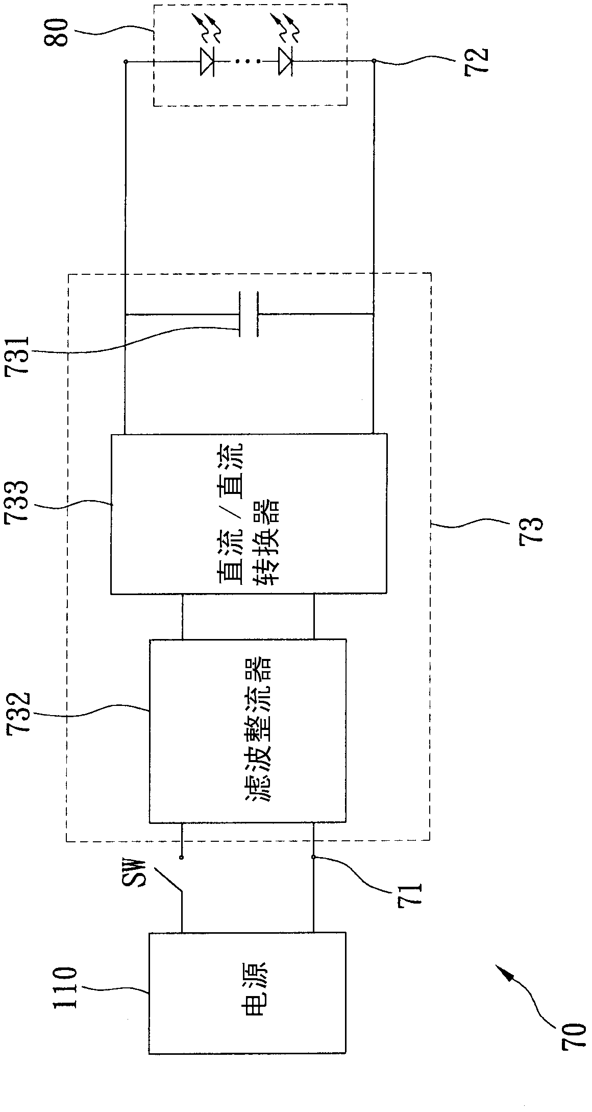
[0025] see image 3 , the first preferred embodiment of the present invention includes a power processing device 10 and a plurality of light-emitting diodes (Light-emitting diode, LED) 20, the power processing device 10 is used to receive and convert the electric energy of a power source 100 for the light emitting Diode 20, in this embodiment, the power supply 100 is the AC power supply provided by the power company, but it is not limited thereto, and it can also be converted to a power generation energy storage system (such as wind power generation, solar power generation, Geothermal power generation, etc.) generated DC power or AC power. The power processing device 10 includes an input port 11, an output port 12, a power conversion module 13 and a discharge module 14, wherein:

[0026] The input port 11 is used to electrically connect with the power source 100 .

[0027] The output port 12 is used to electrically connect with the LED 20 .

[0028] The power conversion mod...


PUM


Abstract

The invention discloses a power supply processing device, which comprises an input port, an output port, a power supply converting module and a discharging module, wherein the input port is used for connecting with a power supply; the output port is used for connecting with at least one light-emitting diode; the power supply converting module is connected with the input port and the output port, and is provided with an equivalent capacitor which is connected in parallel with the light-emitting diode; the power supply converting module is used for receiving the power supply and converting into electric energy of a preset voltage or current form, and outputting to the light-emitting diode through the output port; the discharging module is connected with the power supply converting module, and is provided with a resistor; when the power supply is used for supplying power to the power supply converting module, the discharging module is used for controlling the resistor of the discharging module to be disconnected from the equivalent capacitor; and when the power supply stops supplying power to the power supply converting module, the discharging module is used for controlling the resistor of the discharging module to be connected in parallel with the equivalent capacitor.

Description

technical field [0001] The present invention is related to power supply, more specifically, a power processing device applicable to light-emitting diodes and a discharge control method thereof. Background technique [0002] With the advancement of optical technology, the technology and application of light-emitting diodes (LEDs) are becoming more and more mature, and light-emitting diodes are small in size, fast in response, long in life, not easy to attenuate, strong in appearance, resistant to vibration, and can emit light in full color (Including invisible light), low loss, small heat radiation, easy mass production, etc. Therefore, more and more light sources of lamps are replaced by light-emitting diodes (LEDs) instead of traditional lamps or bulbs. [0003] see figure 1 , is a circuit structure diagram of a power processing device 70 used in common light-emitting diodes, the power processing device 70 includes an input port 71, an output port 72 and a power conversion...

Claims


Application Information

Patent Timeline
Patent Type & Authority Applications(China)
IPC IPC(8): H05B37/02
Inventor 赖文上
Owner HEP TECH
Why Eureka
Try Eureka