Pressure-sharing structure of double-tower-type gas separation equipment

A technology of gas separation and pressure equalization structure, which is applied in the direction of separation methods, dispersed particle separation, chemical instruments and methods, etc. It can solve the problems of not achieving the pressure equalization effect, low product gas concentration, and low gas production volume, etc., and achieve pressure equalization Good effect, reasonable trachea arrangement, and the effect of increasing gas production

Inactive Publication Date: 2013-04-24
HANGZHOU SHENGDA MECHANICAL & ELECTRICAL HI TECH CO LTD
View PDF2 Cites 0 Cited by
  • Summary
  • Abstract
  • Description
  • Claims
  • Application Information

AI Technical Summary

Problems solved by technology

[0002] Double-tower gas separation equipment (such as nitrogen and oxygen generators) includes two adsorption towers (A tower and B tower). When A tower is working, B tower is regenerated. After switching, B tower is working. A tower is regenerated, and the two towers are cycled. To achieve uninterrupted work, during the switching process, the air pressure in tower A and tower B needs to be equalized. At present, the upper end of tower A is connected to the upper end of tower B, and the lower end of tower A is connected to the lower end of tower B to realize the connection between tower A and tower B. Pressure equalization from top to bottom and bottom to bottom, but the air pressure at the upper end of Tower A and Tower B is much higher than the air pressure at the lower end of the two towers. Good pressure equalization effect, resulting in low product gas concentration and low gas production volume produced by the gas separation equipment

Method used


Image

  • Pressure-sharing structure of double-tower-type gas separation equipment
  • Pressure-sharing structure of double-tower-type gas separation equipment
  • Pressure-sharing structure of double-tower-type gas separation equipment

Examples


Embodiment Construction

[0020] The present invention will be further described below with reference to the accompanying drawings.

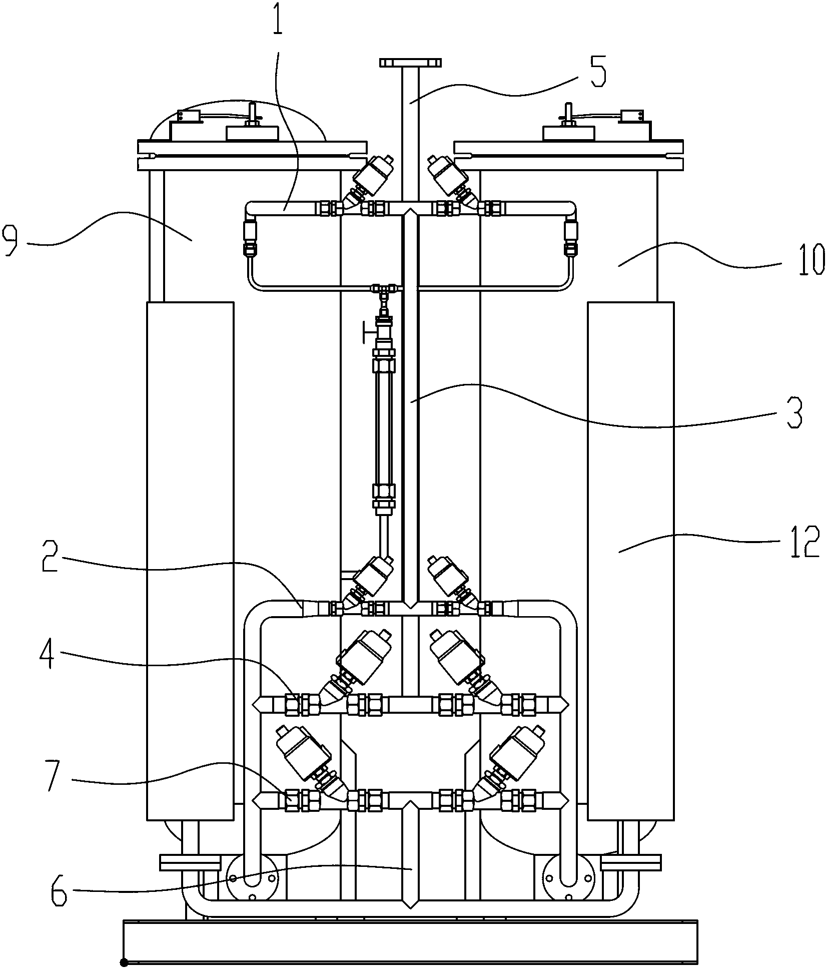
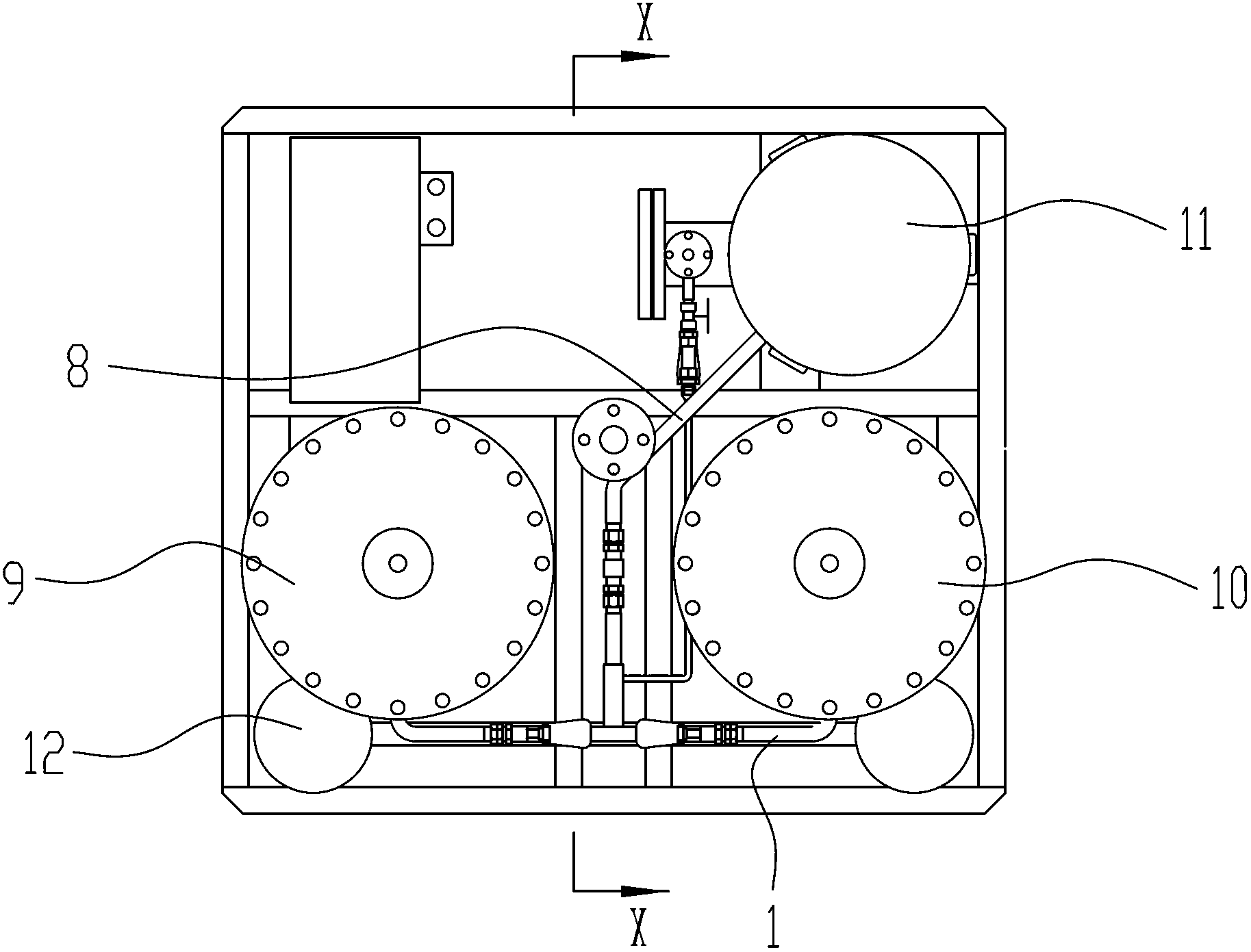
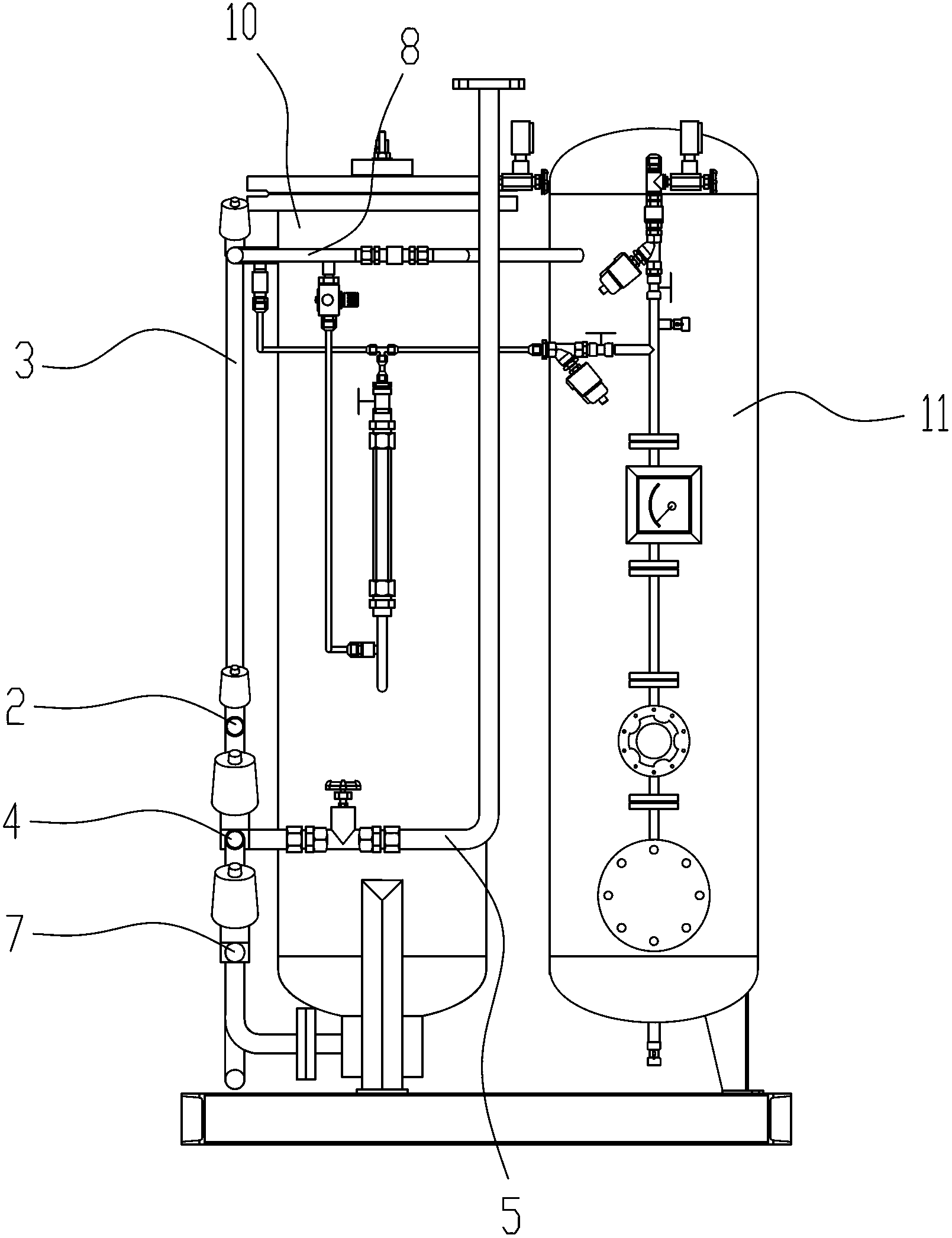
[0021] Such as Figure 1-Figure 4 As shown, the pressure equalization structure of a double-tower gas separation device described in this embodiment includes two adsorption towers, that is, tower A 9 and tower B 10 on the right side of tower A, and the upper ends of the tower body of the two adsorption towers are There is an airflow output port, and an airflow input port is opened at the lower end. The two adsorption towers form an airflow channel through a pressure equalization tube, and the output port of one tower is only connected with the input port of the other tower during pressure equalization.

[0022] The pressure equalizing pipe includes a first gas pipe 1 connected to the output ports of the two adsorption towers and a second gas pipe 2 connected to the input ports of the two adsorption towers. The first gas pipe 1 and the second gas pipe 2 are provided with ...


PUM


Abstract

The invention provides a pressure-sharing structure of double-tower-type gas separation equipment. The pressure-sharing structure of the double-tower-type gas separation equipment solves the problems that a top-top pressure-sharing and bottom-bottom pressure-sharing mode is adopted at present, and finish product gas manufactured by equipment is low in concentration and yield. The pressure-sharing structure of the double-tower-type gas separation equipment comprises two adsorbing towers, and is characterized in that a gas flow outlet is formed at the upper end of a tower body of each adsorbing tower, a gas flow inlet is formed at the lower end of the tower body of each adsorbing tower, the two adsorbing towers form a gas flow channel through a pressure-sharing pipe, and the gas flow outlet of one of the two adsorbing towers is only communicated with the gas flow inlet of the other adsorbing tower when the two adsorbing towers are in pressure-sharing. Due to the fact that a top-bottom intersecting pressure-sharing mode is used for replacing the traditional top-top pressure-sharing and bottom-bottom pressure-sharing mode, gas pressure difference among ends of the two adsorbing towers is enabled to be small, a pressure-sharing effect is good, equipment finish product gas concentration is improved, gas yield is increased, and gas pipes are reasonably arranged, operation is convenient, and a basic gas guide function of the two adsorbing towers in a production process is achieved.

Description

technical field [0001] The invention relates to the technical field of gas separation equipment, in particular to a pressure equalization structure of double-tower gas separation equipment. Background technique [0002] Double-tower gas separation equipment (such as nitrogen generator and oxygen generator) includes two adsorption towers (A tower and B tower). When A tower is working, B tower is used for regeneration. After switching, B tower works and A tower is regenerated. To achieve uninterrupted work, during the switching process, the air pressure in Tower A and Tower B needs to be equalized. At present, the upper end of Tower A is connected to the upper end of Tower B, and the lower end of Tower A is connected to the lower end of Tower B to realize the connection between Tower A and Tower B. Pressure equalization from top to bottom and bottom to bottom, but the air pressure at the upper end of Tower A and Tower B is much greater than the air pressure at the lower end of...

Claims


Application Information

Patent Timeline
IPC IPC(8): B01D53/02
Inventor 赵冲
Owner HANGZHOU SHENGDA MECHANICAL & ELECTRICAL HI TECH CO LTD
Why Eureka
Try Eureka