Driving device in micro-flow pipeline

An internal drive and pipeline technology, applied in the field of fluid mechanics, can solve problems such as weakening the accuracy of test results and sample contamination, and achieve the effects of increasing surface area, reducing pollution, and improving reaction efficiency

Active Publication Date: 2013-04-24
DAAN GENE CO LTD
View PDF6 Cites 8 Cited by
  • Summary
  • Abstract
  • Description
  • Claims
  • Application Information

AI Technical Summary

Problems solved by technology

[0006] 1. When it is necessary to detect multiple indicators of a fluid, multiple samples of the fluid need to be tested. Since different indicators correspond to different samples, the accuracy of the test results will be greatly weakened.
[0007] 2. When multiple or multiple indicators are detected through a sample tissue, the sample will be contaminated due to the need for manual operation

Method used


Image

  • Driving device in micro-flow pipeline
  • Driving device in micro-flow pipeline
  • Driving device in micro-flow pipeline

Examples


Embodiment 1

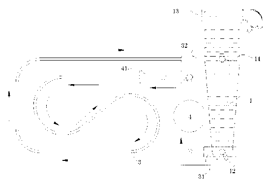
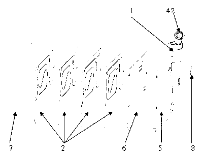
[0029] Further, the fluid chamber 1 also includes a loading port 13 for loading fluid into the fluid chamber 4 , and a sealing cover 42 is provided on the loading port.

[0030] Example 2

Embodiment 2

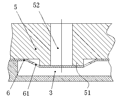
[0032] like image 3 As shown, further, the liquid inlet 31 is provided with a first one-way valve, and the fluid flows from the fluid chamber 1 to the vibration chamber 4 through the first one-way valve. The structure of the first one-way valve is: The first boss 51 on the top and the first overflow groove 61 provided on the vibrating membrane 6, the first boss 51 protrudes toward the direction of the channel membrane, the first boss 51 is provided with a small hole 52, and the small hole 52 passes through the substrate 5 The channel provided on the top is connected to the fluid chamber 1, and the fluid enters the one-way valve through the channel. The first overflow groove 61 on the vibrating membrane 6 is set outside the first boss 51, specifically around the small hole 52. , the first overflow groove 61 is used to release the fluid flowing out from the small hole 52 into the microfluidic pipeline 3 provided on the channel membrane 2, so the first overflow groove 61 include...


PUM


Abstract

The invention provides a driving device in a micro-flow pipeline. The driving device comprises a fluid chamber and a channel membrane, wherein the micro-flow pipeline and a vibrating chamber are arranged on the channel membrane; the fluid chamber comprises a recycling hole and an output hole; an input end of the vibrating chamber is connected with the output hole; the micro-flow pipeline comprises a liquid inlet and a liquid outlet; the liquid outlet is connected with the recycling hole; the liquid inlet is connected with an output end of the vibrating chamber; and the vibrating chamber is used for providing power, so that a fluid moves to the recycling hole from the output hole of the fluid chamber via the vibrating chamber and the micro-flow pipeline; and according to the technical scheme provided by the invention, the consumption amounts of samples and reagents are obviously reduced, the surface area of a fluid environment is increased, the reaction efficiency is improved and the environment pollution caused by waste dump generated by experiments is also reduced; high-flux and automatic control of the experiments can be achieved; and moreover, through accurately controlling a fine structure of a micro-valve micropump, great flexibility is obtained in experimental study time and spatial resolution, and huge advantages are also obtained.

Description

technical field [0001] The invention relates to the technical field of fluid mechanics, in particular to a driving device in a microfluidic pipeline. Background technique [0002] At present, the automatic or manual processing of fluids—whether it is samples or reagents—has become the basic and main work in the laboratory. Faced with a variety of fluid processing tasks, laboratories have to increase manpower or increase investment in automated equipment to Complete work tasks on time, despite this, the consumption of time, space, reagents, samples, laboratory consumables, manpower, and other resources brought about by the processing of a large amount of fluids, as well as the waste liquid and waste generated after fluid processing are still considerable. If the invention and application of a method can integrate the functions of one or several physical laboratories into a small consumable, the samples (very small amount) and reagents (very small amount) are loaded in this co...

Claims


Application Information

Patent Timeline
Patent Type & Authority Applications(China)
IPC IPC(8): B01L3/00
Inventor 洪俊安周诗寒谢剑锋区仲荣
Owner DAAN GENE CO LTD
Why Eureka
Try Eureka