Angular fixer

A fixer and angle-shaped technology, applied in the field of angle-shaped fixers, can solve problems such as safety hazards of simple hoisting tools, strong dependence on large hoisting equipment, inconvenient production, etc., and achieve the effect of saving tedious work, reducing potential safety hazards, and simple structure

Active Publication Date: 2013-04-24
天津博宜特科技有限公司
6 Cites 2 Cited by

AI-Extracted Technical Summary

Problems solved by technology

This operation process not only requires a lot of manpower, but also relies heavily on large-scale hoisting equipment, and sometimes even temporarily erects simple ...

Method used

[0031] In the present embodiment, the radial direction of the adjusting arm 5 is provided with a mounti...

Abstract

The invention provides an angular fixer which comprises two fixing frames and two adjusting arms. The two fixing frames are fixedly connected on equipment used for fixedly connecting a bearing seat and are positioned on two sides of the bearing seat, the adjusting arms and the fixing frames are hinged through a connecting shaft, the two adjusting arms are hinged through a connecting shaft, a screw hole is arranged in the radial direction of each connecting shaft and connected with an adjusting lead screw in a matched manner, and one end of each adjusting lead screw is connected with a winding part which is sleeved on a to-be-fixed part. By the angular fixer, space is saved for demounting the bearing seat and replacing or maintaining a bearing, stroke quantity is increased, dependence on on-site hoisting tools is eliminated, tedious works for erecting simple hoisting tools on site are omitted, manpower resources are saved, potential safety hazards are reduced, and the angular fixer has the advantage of simple structure.

Application Domain

Metal-working hand tools

Technology Topic

EngineeringEquipment use

Image

  • Angular fixer
  • Angular fixer
  • Angular fixer

Examples

  • Experimental program(1)

Example Embodiment

[0026] Hereinafter, a specific embodiment is listed in conjunction with the drawings to further illustrate the present invention.
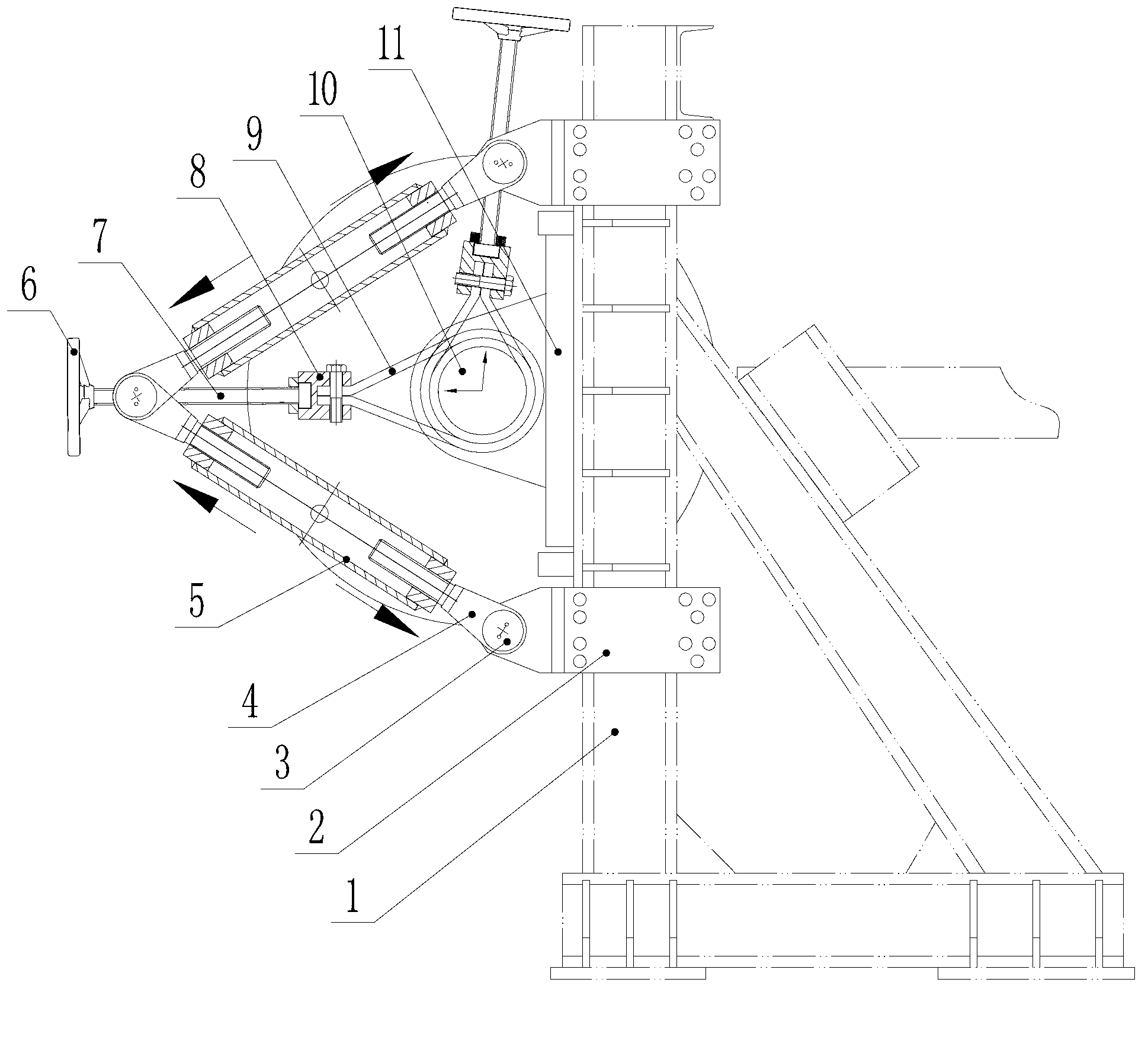
[0027] Such as figure 1 As shown, this embodiment is an angular holder, including two fixing frames 2 and an adjusting arm 5; both fixing frames are fixed on the equipment used to fix the bearing housing 11, and the two fixing frames 2 are located Both sides of the bearing seat 11; between the adjusting arm 5 and the fixed frame 2, and between the two adjusting arms 5 are hinged by a connecting shaft 3; the connecting shaft 3 is provided with a screw hole in the radial direction, and the screw hole is matched and connected with an adjusting screw 7. One end of the adjusting screw 7 is connected with a winding piece, and the winding piece is sleeved on the piece to be fixed.
[0028] Such as figure 1 As shown, in this embodiment, the equipment for fixing the bearing is the frame 1, the winding part is a flexible winding part, and the hoisting belt 9 is selected, and the hoisting belt is sleeved on the drum shaft 10; one end of the adjusting screw 7 passes through a lock rope joint 8 is connected with the lifting strap 9, and the other end of the adjusting screw is provided with an operating handle or hand wheel 6.
[0029] Such as figure 2 , image 3 As shown, in this embodiment, the front end of the fixing frame 2 is provided with a U-shaped body 21, two side arms of the U-shaped body 21 are provided with through holes, and the through holes are connected with the connecting shaft 3 in cooperation;
[0030] Such as Figure 4 As shown, the adjusting arm 5 in this embodiment is a long hollow cylindrical structure, and the center of the two ends of the adjusting arm 5 is provided with screw holes 51 of different rotation directions; both ends of the adjusting arm 5 are provided with an adjusting frame 4, such as Figure 5 , Image 6 As shown, the adjusting frame 4 is provided with a U-shaped body 41 and a screw 42. The two side arms of the U-shaped body 41 are provided with through holes, and the through holes are connected with the connecting shaft. The screw 42 of the adjusting frame 4 and the adjusting arm 5 The screw holes 51 on the upper part are matched and connected.
[0031] In this embodiment, a mounting hole for installing the handle is provided in the radial direction of the adjusting arm 5, which is convenient for adjusting the length of the adjusting arm 5.
[0032] In this embodiment, analyzing from the vertical direction, the unilateral weight of the drum shaft is transmitted to the uppermost connecting shaft 3 through the hoisting belt 9, the lock rope joint 8, the adjusting screw 7 and other components. The fixing bolts on the bearing housing 11 can be opened and the roller shaft 10 can still be fixed.
[0033] Analyzed from the horizontal direction, the engagement position of the connecting shaft 3 on the adjusting screw 7 is changed by rotating the hand wheel so that the roller can achieve partial displacement in the horizontal direction. Since the two fixing frames 2, the adjusting frame 4, and the adjusting arm 5 are connected by three connecting shafts 3, a triangular structure is formed. The two fixing frames 2 and the frame 1 have been fixed, and the two ends of the two tubular adjusting arms 5 The thread direction is different. Therefore, by rotating the tubular adjusting arm 5, the length of one side of the triangle can be adjusted. If the two sides of the triangle are increased by rotating the tubular adjusting arm 5 at the same time, the horizontal displacement of the roller shaft can also be realized. It can be seen from this that this embodiment increases the stroke of the bearing or the bearing seat, making it easier to disassemble and adjust, and save working space at the same time.
[0034] In summary, through this device, the roller shaft 10 can be kept on the frame, while saving space for disassembling the bearing seat, replacing or maintaining the bearing, getting rid of the dependence on on-site hoisting tools, and saving on site The tedious work of temporarily erecting simple hoisting tools saves human resources and reduces potential safety hazards.
[0035] An embodiment of the present invention has been described in detail above, but the content is only a preferred embodiment of the present invention, and cannot be considered as limiting the scope of implementation of the present invention. All equal changes and improvements made in accordance with the scope of the application of the present invention should still fall within the scope of the patent of the present invention.

PUM

no PUM

Description & Claims & Application Information

We can also present the details of the Description, Claims and Application information to help users get a comprehensive understanding of the technical details of the patent, such as background art, summary of invention, brief description of drawings, description of embodiments, and other original content. On the other hand, users can also determine the specific scope of protection of the technology through the list of claims; as well as understand the changes in the life cycle of the technology with the presentation of the patent timeline. Login to view more.

Similar technology patents

Hydraulic brake

InactiveCN101482154Agood for coolingsave space
Owner:XUZHOU WUYANG TECH

Air managing system of lithium-air secondary battery pack

ActiveCN103259065Asave spacereduce noise
Owner:CHANGCHUN INST OF APPLIED CHEMISTRY - CHINESE ACAD OF SCI

Electronic device and radiating casing thereof

Owner:中山市云创知识产权服务有限公司

Classification and recommendation of technical efficacy words

  • save space

Multi-node management method and system

Owner:XFUSION DIGITAL TECH CO LTD

Chemiluminescence immunoassay device

InactiveCN104777321Asave spaceHigh detection throughput
Owner:TSINGHUA UNIV +1

Protective frame for mobile communication device

InactiveUS20130088815A1minimize size and weightsave space
Owner:TAER INNOVATION

Folding type aerial photography aircraft

InactiveCN105035303Areduce volumesave space
Owner:WUXI MIRACLE SCI & TECH CO LTD
Why Eureka
Try Eureka