Double-salient liquid cooling eddy current retarder with front-loading gearbox

A technology of eddy current retarder and retarder, which is applied in the direction of asynchronous induction clutch/brake, motor, electric vehicle, etc. It can solve the problems of affecting the service life of the gearbox, reducing the service life of the clutch disc, and the impact of the gearbox gear. , to achieve the effects of compact structure, increased service life, and large equivalent torque

Active Publication Date: 2013-04-24
YANGZHOU ANXING ELECTROMECHANICAL TECH
View PDF5 Cites 10 Cited by
  • Summary
  • Abstract
  • Description
  • Claims
  • Application Information

AI Technical Summary

Problems solved by technology

[0004] The invention patent named "a liquid-cooled self-excited eddy current retarder with a salient pole structure" (patent application number is 201210061808.1) and the invention named "a liquid-cooled electric eddy current retarder with a salient pole structure" The eddy current retarder disclosed in the patent (patent application No. 201210061975.6) adopts a salient pole structure. If these two structures are used as a front retarder, the moment of inertia of the rotor is too large, and the vehicle is replaced. When it is in gear, it will cause an impact on the gearbox gear and affect the service life of the gearbox
The invention patent (patent application number 200810132271.7) titled "Front Gearbox Liquid-cooled Permanent Magnetic Retarder" discloses a front-mounted retarder. A cylinder is used to connect the high-speed rotating clutch plate with the stationary clutch plate. Once the friction plate contacts, the rotor of the retarder will start to rotate immediately, and the retarder will generate braking torque. This mode of operation will seriously reduce the service life of the clutch plate.

Method used


Image

  • Double-salient liquid cooling eddy current retarder with front-loading gearbox

Examples


Embodiment Construction

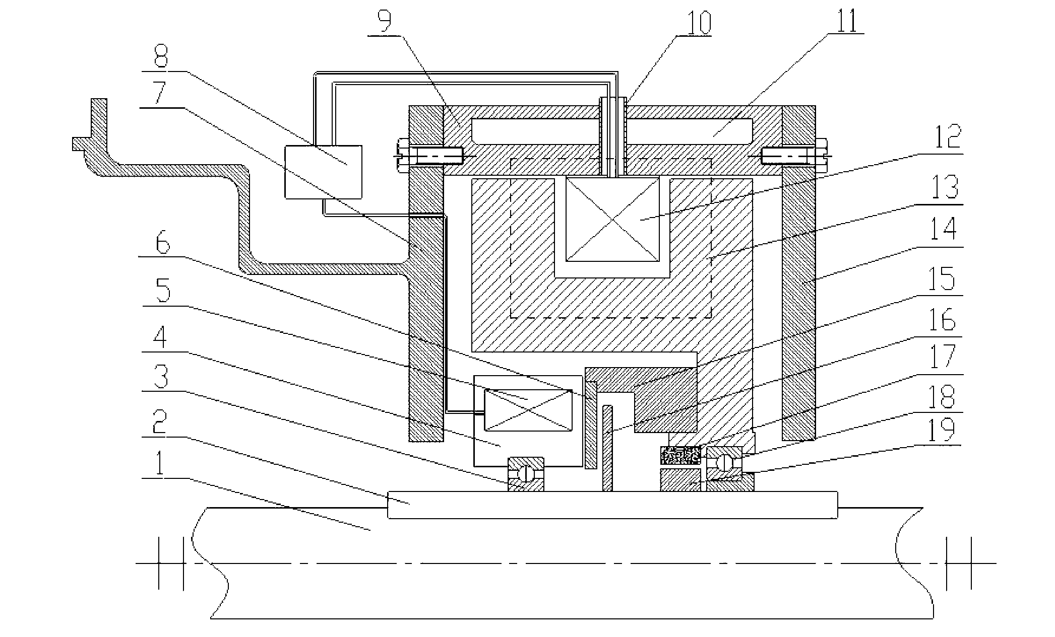
[0019] Specific embodiments of the present invention will be further described below in conjunction with the accompanying drawings.

[0020] Such as figure 1 As shown, the clutch yoke 4 is connected to the key 2 and the transmission shaft 1 through the yoke support bearing 3, the clutch coil 5 is connected to the control module 8, and the driven disc friction plate group 6 in the clutch disc 15 is connected to the retarder rotor through screws. 13, and the pressure plate 16 is connected with the transmission shaft 1 through the key 2. The retarder coil 12 is concentratedly wound to form an independent coil, which is fixed on the inner wall of the retarder stator 9 and installed between two salient poles of the retarder rotor 13 . The wires of the retarder coil 12 are led out through the wire sleeve 10 passing through the retarder stator 9 and connected to the control module 8 , and the control module 8 controls the clutch coil 5 and the retarder coil 12 . The retarder rotor ...


PUM


Abstract

A double-salient liquid cooling eddy current retarder with a front-loading gearbox belongs to the field of automobile braking. The double-salient liquid cooling eddy current retarder structurally comprises a clutch magnet yoke, a clutch coil, a clutch disc, a retarder rotor, a retarder stator, a retarder coil and a control module. The retarder is disposed between an engine and the gearbox. Torque is amplified by speed reduction of the gearbox, so that braking effect of the retarder is improved. The retarder rotor is a tooth-shaped rotary disc and connected with a transmission shaft through a support bearing. A permanent magnet is mounted on the inner side of the retarder rotor. The permanent magnet drives the retarder rotor to rotate to allow approximate synchronous rotation of the retarder rotor with an automotive spindle, and accordingly loss during operation of clutch friction plates is reduced. By the permanent magnet, approximate synchronous rotation of the retarder rotor with the automotive spindle is achieved, friction plate loss during braking of the retarder is reduced, a work mode that the clutch is in prior to the retarder is used, and accordingly better braking effects and heat fading compared with traditional eddy current retarders are achieved. In addition, the double-salient liquid cooling eddy current retarder is compact in structure and low in size and weight.

Description

technical field [0001] The invention relates to an eddy current retarder, which generates eddy current braking torque by cutting magnetic induction lines on a rotating and non-contact metal arc surface, and assists braking of automobiles. The invention relates to a liquid-cooled double-salient structure liquid-cooled retarder, which belongs to the field of automobile braking. Background technique [0002] The eddy current retarder is a kind of auxiliary braking device for automobiles. When the rotor rotates with the drive shaft, the air gap magnetic flux density changes periodically with the rotation of the rotor, and the eddy current potential is induced on the inner surface of the stator and generates an eddy current. , so as to generate braking torque, the car converts kinetic energy into heat energy through the medium of magnetic field and consumes it, thereby achieving the effect of deceleration and braking. [0003] The biggest feature of the eddy current retarder is ...

Claims


Application Information

Patent Timeline
Patent Type & Authority Applications(China)
IPC IPC(8): B60L7/28H02K49/04
CPCY02T10/64
Inventor 李德胜张凯杜肖尹汪雷
Owner YANGZHOU ANXING ELECTROMECHANICAL TECH
Why Eureka
Try Eureka