Tail device and tail dragging method

A hoisting method and equipment technology, applied in the direction of transportation and packaging, load hanging components, etc., can solve the problems of large manpower investment, equipment resource occupation, and long preparation period for auxiliary equipment, and achieve low construction requirements, reduce hoisting costs, and purchase low cost effect

Inactive Publication Date: 2013-04-24
SANY HEAVY IND CO LTD (CN)
View PDF4 Cites 34 Cited by
  • Summary
  • Abstract
  • Description
  • Claims
  • Application Information

AI Technical Summary

Problems solved by technology

[0003] For the traditional tail row lifting method, it is necessary to use a hoist for towing, traction and back sliding, and use roller bars or laying tracks to realize the movement. Auxiliary equipment and manpower input are large, the operation is complicated and the preparation period is long, and the tail The support point of the tail row is set at the lower end of the equipment. When the equipment is turned upright during the hoisting process, it usually needs to cross the critical point of the center of gravity, which will bring a large shaking impact. The tail row needs to bear almost all the weight of the equipment, so It is rarely used in mechanized hoisting
[0004] For the lifting and lifting method, although the above-mentioned shortcomings of the tail-sliding and tail-sliding lifting method can be avoided, it is necessary to configure large-scale lifting equipment for sliding the tail, especially crawler cranes, which not only occupy equipment resources, but also have high project construction costs.

Method used


Image

  • Tail device and tail dragging method
  • Tail device and tail dragging method
  • Tail device and tail dragging method

Examples


Embodiment Construction

[0048] It should be noted that, in the case of no conflict, the embodiments of the present invention and the features in the embodiments can be combined with each other. The present invention will be described in detail below with reference to the accompanying drawings and examples.
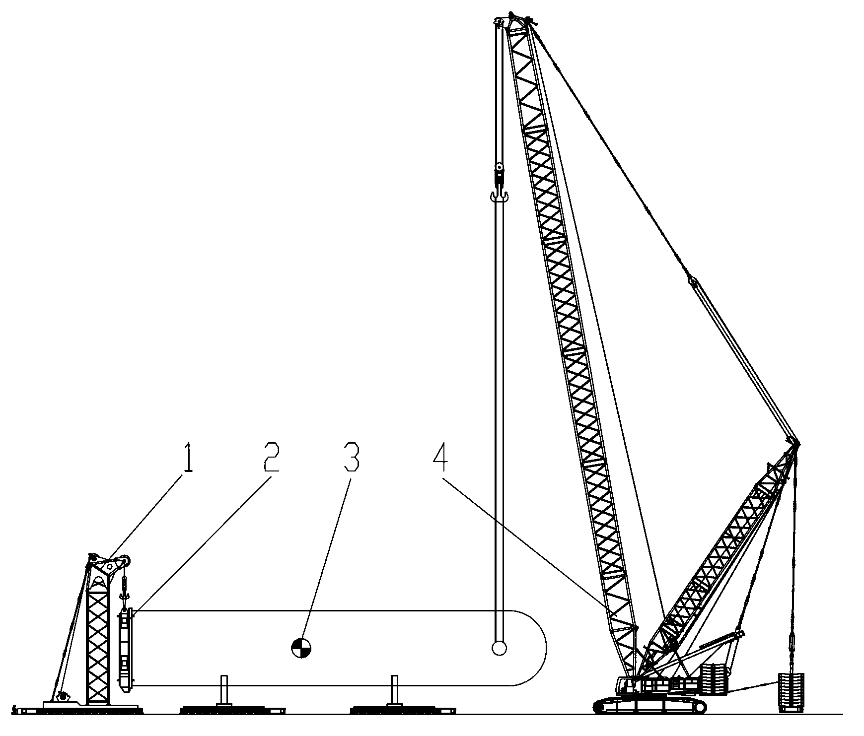
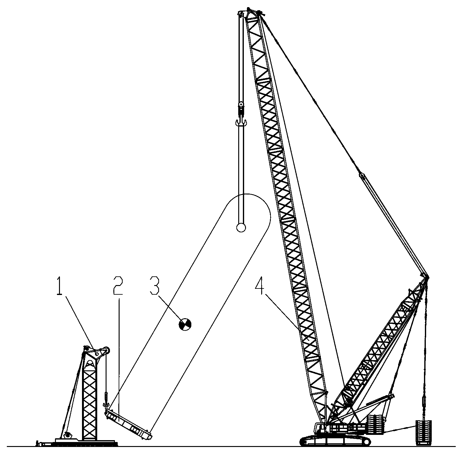
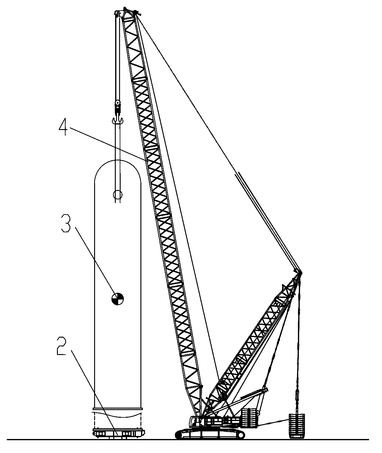
[0049] The basic idea of ​​the present invention is: in order to solve the large shaking impact caused by the need to cross the critical point of the center of gravity during the hoisting process, the present invention provides a tail-sliding equipment and a hoisting method, which can ensure that the main lifting equipment and the tail-sliding The line connecting the stress point of the platoon is always above the center of gravity of the equipment being hoisted. On the one hand, it reduces the load bearing of the platoon at the rear, and on the other hand, it ensures stable and balanced operation and eliminates potential safety hazards.

[0050] Figure 1a-1c Shown is a schematic diagram of the...


PUM


Abstract

The present invention discloses a tail device and a tail dragging method. The tail device comprises: a tail end row which at least comprises a boom system, a travelling mechanism and a lifting mechanism, wherein the boom system is provided with a lifting mechanism and is supported on the travelling mechanism; and a tailstock which is used for being removably fixed to the lower part of a lifted device, and is provided with lifting holes. In the process of lifting the lifted device from the ground, the lifting mechanism is in hanging connection with the lifting holes, and the lifting holes are located at the end deviating from the ground. When the tail device is use for lifting a device, the center of gravity of the lifted device can be guaranteed to be always located below a connection line between the lifting point of main lifting equipment and the lifting point or the support point of the tail end row. The tail device has the advantages of good security, small weight borne by the tail end row, low lifting cost, etc.

Description

technical field [0001] The present invention mainly relates to the field of hoisting, in particular to a tail-running device and a tail-running hoisting method using the tail-running device and main lifting equipment. Background technique [0002] For large-scale equipment that needs to be flipped and hoisted, such as reactors in petrochemical engineering, the hoisting process needs to flip the reactor from a horizontal state to a vertical state. In the traditional hoisting, the tail row or lifting method is generally used. Usually, the main lifting equipment is used at one end of the hoisted equipment, and the tail row or tail crane is used at the other end. [0003] For the traditional tail row lifting method, it is necessary to use a hoist for towing, traction and back sliding, and use roller bars or laying tracks to realize the movement. Auxiliary equipment and manpower input are large, the operation is complicated and the preparation period is long, and the tail The su...

Claims


Application Information

Patent Timeline
Patent Type & Authority Applications(China)
IPC IPC(8): B66C13/00B66C13/08
Inventor 李明奇刘金江张啸飞王宝玉姜春华
Owner SANY HEAVY IND CO LTD (CN)
Why Eureka
Try Eureka