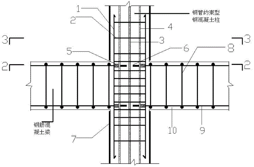
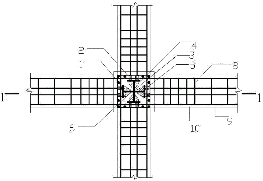
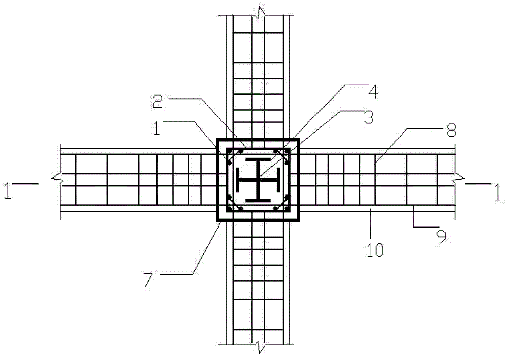
Joint structure of steel-pipe-restraining steel concrete columns and reinforced concrete beams

A technology for reinforced concrete beams and concrete columns, which is applied to building structures and buildings, can solve the problems of inability to use the joint form, and achieve the effects of reducing welding workload, reliable transmission, and convenient construction.

Inactive Publication Date: 2013-04-24
YANGTZE UNIVERSITY
View PDF6 Cites 20 Cited by
  • Summary
  • Abstract
  • Description
  • Claims
  • Application Information

AI Technical Summary

Problems solved by technology

On the other hand, there is only concrete in the steel pipes of CFST columns, but there is not only concrete but also continuous section steel in the steel pipes of CFST columns. Therefore, the joint form of CFST columns and reinforced concrete beams cannot be used.

Method used


Image

  • Joint structure of steel-pipe-restraining steel concrete columns and reinforced concrete beams
  • Joint structure of steel-pipe-restraining steel concrete columns and reinforced concrete beams
  • Joint structure of steel-pipe-restraining steel concrete columns and reinforced concrete beams

Examples


Embodiment Construction

[0021] The present invention will be further described below in conjunction with drawings and embodiments.

[0022] A joint structure for the connection between steel pipe-constrained steel concrete columns and reinforced concrete beams, consisting of vertical connecting steel bars 1, column stirrups 2, steel webs 3, steel flanges 4, sleeves 5, stiffeners 6, steel pipes 7, and beams Stirrups 8, beam main reinforcement 9, and concrete 10; the section steel welded by section steel web 3 and section steel flange 4 is a cross-shaped structure; Sleeve 5. Stiffeners 6 are welded on the inner side of the steel flange 4 corresponding to the sleeve 5; the steel pipe 7 is interrupted at the node; the section steel passes through the node continuously from bottom to bottom; the vertical connecting steel bar 1 is inserted into the node The inside of the steel pipe 7 at the upper and lower sections is bound with dense column hoops 2 and vertical connecting steel bars 1 to form a reinforcem...


PUM


Abstract

The invention relates to a joint structure of steel-pipe-restraining steel concrete columns and reinforced concrete beams. The joint structure is characterized in that a profile steel is in a cross structure and is formed by a profile steel web (3) and profile steel flanges (4) through welding. At joints, sleeves (5) are welded on the outer sides of the profile steel flanges (4) of sides of the profile steel, and stiffening ribs (6) are welded on the inner sides of the profile steel flanges (4) corresponding to the sleeves (5). Gaps are arranged between steel pipes (7) at the joints, and the profile steel penetrates through the joints from bottom to top in a continuous mode. Vertical connection steel bars (1) are inserted in the inner sides of the upper segment and the lower segment of the steel pipes (7) arranged at the joints. Columnar stirrups (2) are used for being bound with the vertical connection steel bars (1) to form a reinforcement cage. A part of beam main ribs (9) in a beam penetrate through continuously from sides of the profile steel flanges (4), and the part of the beam main ribs (9) are connected with the sleeves (5) welded on the outer sides of the profile steel flanges (4) in a welding mode. The joint structure is good in mechanical property, simple in design, convenient to construct, and low in cost, and has no special requirement on welding.

Description

Technical field: [0001] The invention relates to a node structure for connecting a steel pipe-constrained steel concrete column and a reinforced concrete beam, and belongs to the technical field of civil engineering structure design. Background technique: [0002] The steel pipe bound steel concrete column is a new type of heavy-duty column, that is, the steel pipe is cut off at both ends or in the middle by a certain distance, the steel pipe is set in the steel pipe, and then the concrete is filled in the steel pipe. The steel pipe confined steel concrete column takes into account the advantages of the steel pipe concrete column and the steel concrete column comprehensively. The steel pipe imposes a continuous restraint on the concrete, which increases the compressive strength of the concrete and improves the ductility of the concrete; the presence of the steel improves the shear resistance of the column. capacity; the existence of concrete makes up for the shortcomings of ...

Claims


Application Information

Patent Timeline
Patent Type & Authority Applications(China)
IPC IPC(8): E04B1/58
Inventor 杜国锋宋鑫余思平
Owner YANGTZE UNIVERSITY
Why Eureka
Try Eureka