Water boiler with liquid level stabilizing function

A technology of stable liquid level and water boiler, applied in fluid heaters, lighting and heating equipment, etc., can solve the problems of low water level control accuracy, large water level fluctuation range, unstable water output flow, etc., and achieve boiling water output temperature and water flow The output flow is stable, the water level fluctuation range is reduced, and the water level control accuracy is improved.

Active Publication Date: 2013-04-24
博汭电气(苏州)有限公司
View PDF10 Cites 2 Cited by
  • Summary
  • Abstract
  • Description
  • Claims
  • Application Information

AI Technical Summary

Problems solved by technology

[0003] The technical problem to be solved by the present invention is that the water boiler in the prior art has problems such as large fluctuation range of water level, low precision of water level control, unstable output flow of water flow, etc.

Method used


Image

  • Water boiler with liquid level stabilizing function
  • Water boiler with liquid level stabilizing function
  • Water boiler with liquid level stabilizing function

Examples


Embodiment 1

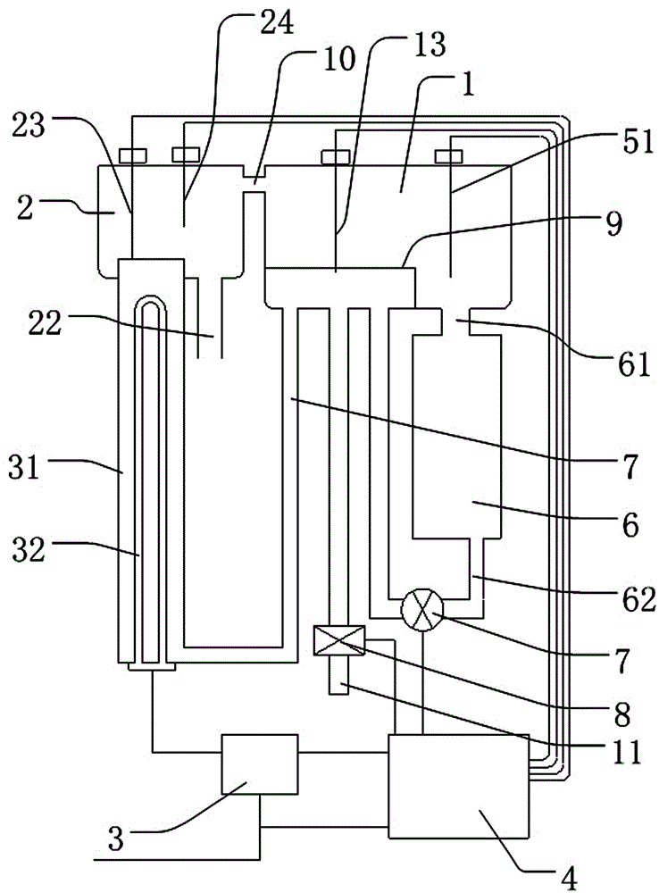
[0043] Such as figure 1 It is a schematic structural diagram of Embodiment 1 of the present invention. The figure shows a water boiler with liquid level stabilization function, including:

[0044] A cold water tank 1 for storing cold water;

[0045] One boiling water tank 2 for storing boiling water;

[0046] A heating pipe 32 for connecting the cold water tank and the boiling water tank;

[0047] The cold water tank 1 is provided with a cold water tank inlet pipe 11 and a cold water tank outlet pipe 12;

[0048] The boiling water tank 2 is provided with a boiling water tank inlet pipe (not shown) and a boiling water tank outlet pipe 22;

[0049] One end of the heating pipe 32 is connected to the cold water tank outlet pipe 12, and the other end is connected to the boiling water tank inlet pipe (not shown);

[0050] A heater 31 is provided in the heating pipe 32 for heating the water in the heating pipe 32;

[0051] An inlet valve 8 is provided on the cold water inlet pipe 11;

[0052] An o...

Embodiment 2

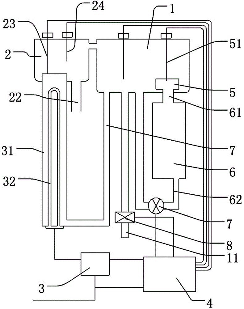
[0070] figure 2 Is a schematic structural diagram of Embodiment 2 of the present invention, such as figure 2 As shown, most of the technical solutions of the second embodiment are the same as those of the first embodiment. The difference technical feature is that the water boiler with liquid level stabilization function also includes a slow flow tube 5, the nozzle of the slow flow tube 5 is high At the bottom of the cold water tank 1, the slow flow chamber 6 is connected to the slow flow pipe 5 through a slow inflow water pipe 61, and the slow outflow water pipe 62 is connected to the bottom of the cold water tank 1. The slow flow pipe 5 is located inside the cold water tank 1.

[0071] After the water level in the cold water tank 1 reaches a certain height (that is, the height of the upper end of the slow flow pipe 5), the water flows out from the upper end of the slow flow pipe 5, flows into the slow flow chamber 6 through the slow inflow water pipe 61, and then flows through ...

Embodiment 3

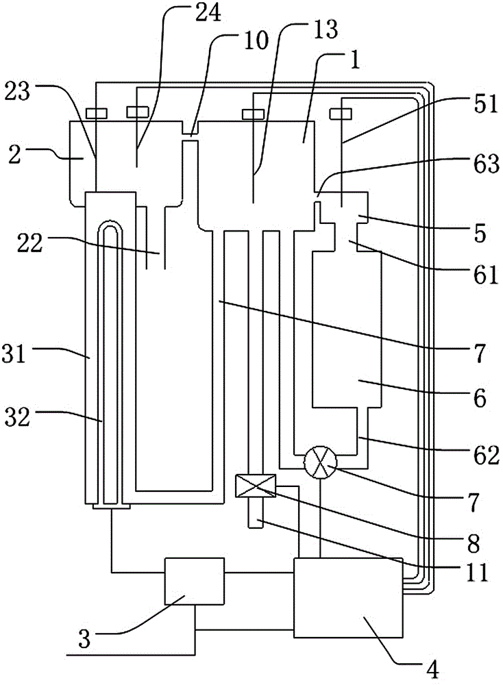
[0075] image 3 It is a schematic diagram of the structure of Embodiment 3 of the present invention, such as image 3 As shown, most of the technical solutions of the third embodiment are the same as those of the second embodiment. The different technical feature is that the slow flow tube 5 is located outside the cold water tank 1, and the slow flow tube 5 is connected to the cold water tank 1 through a slow flow conduit 63. The implementation and technical effects of Example 3 are basically the same as those of Example 2. After the water level in the cold water tank 1 reaches a certain height (that is, the nozzle height of the slow flow duct 63 on the side wall of the cold water tank 1), the water flows from the slow flow duct 63 flows into the slow flow pipe 5, flows into the slow flow chamber 6 through the slow inflow water pipe 61, and then flows back to the cold water tank 1 through the slow outflow water pipe 62. After so many cycles, the water pump 7 provides circulatin...


PUM


Abstract

The invention discloses a water boiler with a liquid level stabilizing function. The water boiler comprises a cold water tank, a boiled water tank and a heating pipe, a heater is arranged in the heating pipe, a water inlet valve is arranged on a water inlet pipe of the cold water tank, a water drain valve is arranged on a water drain pipe of the boiled water tank, the water boiler further comprises a driving unit, a control unit and a slow flow cavity, the control unit is electrically connected with the driving unit, the slow flow cavity is located below the cold water tank and used for forming a cold water circulation, the slow flow cavity is provided with a slow flow water inlet pipe and a flow slow water outlet pipe, the slow flow water inlet pipe and the flow slow water outlet pipe are communicated with the cold water tank, and a water pump is arranged on the slow flow water outlet pipe and electrically connected with the control unit through a wire. The water boiler with the liquid level stabilizing function has the advantages of effectively reducing water level fluctuation range, improving water level control accuracy, and enabling boiled water output temperature and water flow output flow to be stable.

Description

Technical field [0001] The invention relates to a liquid heating device, in particular to a water boiler with a liquid level stabilization function. Background technique [0002] The prior art liquid heating equipment, such as a quick water boiler (patent number ZL200920068344.0), controls the water level in the water tank through a water level sensor. Common liquid level sensors include float type water level sensor controller, float switch type water level controller or conductive water level controller. The above-mentioned various water level controllers have a relatively large water level fluctuation range, low control accuracy, and a great influence on the water flow output flow. Summary of the invention [0003] The technical problem to be solved by the present invention is that the prior art water boiler has problems such as large water level fluctuation range, low water level control accuracy, and unstable water output flow. [0004] The technical scheme disclosed by the p...

Claims


Application Information

Patent Timeline
Patent Type & Authority Applications(China)
IPC IPC(8): F24H9/20
Inventor 朱利辉
Owner 博汭电气(苏州)有限公司
Why Eureka
Try Eureka