Supercharge Your Innovation With Domain-Expert AI Agents!

Detection device for pipe corrosion conditions

A detection device and pipeline technology, which is applied in the direction of material analysis using radiation, can solve the problems of cumbersome disassembly and assembly of the clamping device, heavy workload of flaw detection equipment, and low work efficiency, so as to improve the stability of the device and increase the clamping force , high work efficiency

Inactive Publication Date: 2014-11-05
SICHUAN UNIV
View PDF2 Cites 0 Cited by
  • Summary
  • Abstract
  • Description
  • Claims
  • Application Information

AI Technical Summary

Problems solved by technology

[0006] The pipeline corrosion detection device provided by the present invention solves the problem that the "pipeline weld X-ray omnidirectional detection device" in the prior art is difficult to be directly used in the "pipeline corrosion detection", which not only has a complex structure, but also has low clamping force, The disassembly and assembly of the clamping device is cumbersome, the workload of the manual movement of the flaw detection equipment is large, and the work efficiency is low. The purpose is to provide a detection device dedicated to the corrosion of the bottom of the pipeline.

Method used


Image

  • Detection device for pipe corrosion conditions

Examples


Embodiment 1

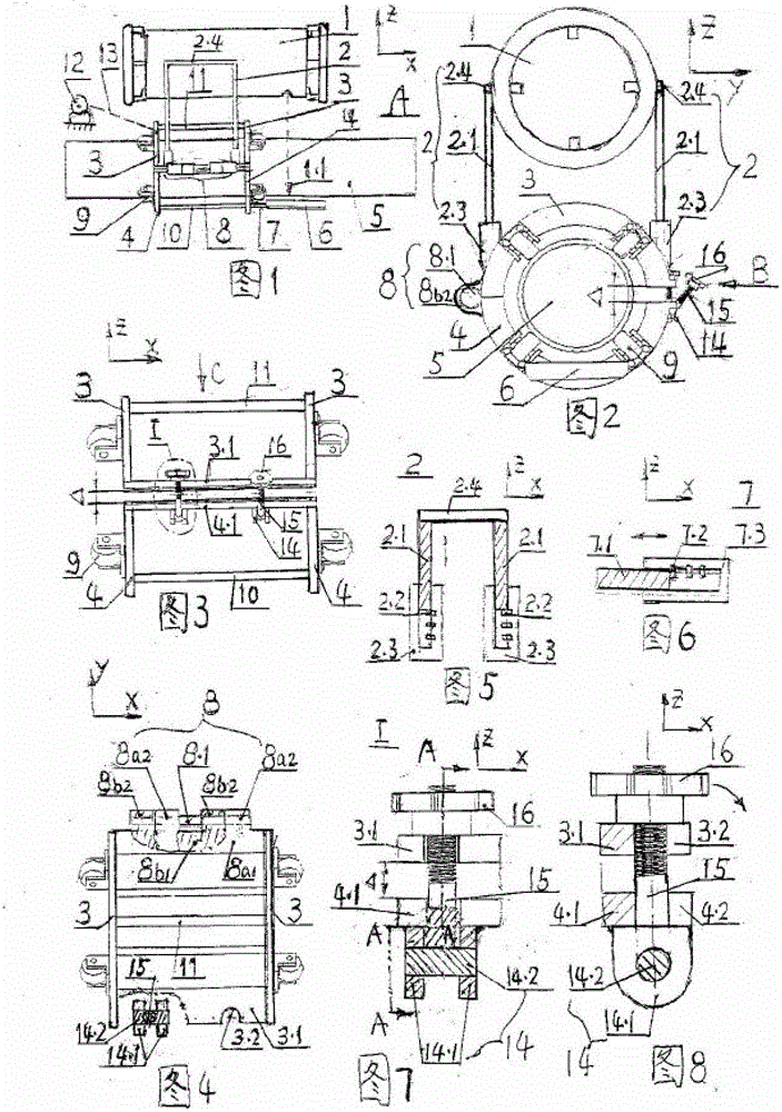
[0023] See figure 1 , figure 2 In this embodiment, the pipeline corrosion detection device is formed as follows: the X-ray machine 1 placed above the pipeline 5 adopts a cermet tube portable X-ray machine, and the detection flat panel 6 placed on the outer bottom of the pipeline adopts an amorphous silicon flat panel detector.

[0024] See figure 1 , image 3 , a clamping ring assembled on the outer circumference of the pipe 5 is respectively arranged on the front and rear ends of the pipe in the axial direction X (see item 3 and item 4 at both ends). See figure 2 , each group of clamping circles has an upper half circle 3 and a lower half circle 4, and each group of upper half circles and lower half circles is connected by a hinge connection 8 along one end of the horizontal Y. The other end is an opening, and there is a gap Δ in vertical Z. See image 3 , there are upper connecting plate 3.1 and lower connecting plate 4.1 respectively between the two upper half circl...

Embodiment 2

[0030] Embodiment 2: This embodiment 2 is identical to embodiment 1 except for the following features.

[0031] See figure 1 , establish the motor 12 and the transmission rope 13, one end of the transmission rope is connected to the output shaft of the motor, and the other end is fixed on the upper half circle or the lower half circle, or is fixed on the upper half circle and the lower half circle at the same time. The number of rotations and the shrinkage length of the transmission rope can be set in the motor according to the length of the pipeline to be tested, and the motor can be controlled to automatically roll axially to detect the corrosion status of the full-length pipeline.


PUM


Abstract

The invention relates to a detection device for pipe corrosion conditions. Two groups of clamping rings each with an upper semi-ring and a lower semi-ring are installed outside of a pipe, one end of the clamping ring is hinged and connected, the other end of the clamping ring is open and provided with a gap, an upper connecting plate and a lower connecting plate are disposed along an axial direction and are fastened by using bolts, an upper handle, a lower hinge mechanism and the like. The upper semi-ring can make an opening and closing rotation to realize surrounding and clamping from the middle portion; the bolts can be rotably clamped, are very simple in assembly and disassembly and have large clamping force and high stability. Wheels capable of rolling on an axial direction of the pipe can be disposed in the clamping ring. The detection device shifts in the axial direction without disassembly and has high efficiency. If an electric motor is employed, an operator can stay away from a ray source. An upper telescopic frame is arranged and supported by an X-ray machine and a lower telescopic rod is fixed on a detection flat plate. The two positions can be adjusted, so that the ray direction and the detection flat plate blow the pipe can be vertically opposite so as to image accurately. The X-ray machine has long service life and good performance. The detection flat plate has uniform sensitivity and resolution, and a large dynamic range. The optimized detection device specialized for corrosion conditions at the bottom of the pipe provided by the invention is suitable for the detection of in service pipes lain in a trench or on the ground.

Description

(1) Technical field: [0001] The utility model relates to a pipeline corrosion state detection device, which belongs to pipeline detection equipment. It belongs to measurement category (G01N) and pipeline category (F17D). (2) Background technology: [0002] Pipeline transportation is an economical, efficient, clean and safe way to solve energy transportation problems. After more than 100 years of development, pipelines have become a huge oil and gas energy transportation tool worldwide. However, due to the long-term use of such pipelines, a series of problems such as corrosion, rust, and small cracks are prone to occur around the pipeline, especially at the bottom of the pipeline. Due to the particularity of the pipeline in service, it is difficult for the detection device to be inserted and installed from both ends of the pipeline, and it is required to install and clamp the middle section of the pipeline as much as possible, which brings certain difficulties to the clampi...

Claims


Application Information

Patent Timeline
Patent Type & Authority Patents(China)
IPC IPC(8): G01N23/18
Inventor 赵武曾杰李小龙尚万胡炳星夏鹏
Owner SICHUAN UNIV
Features
  • R&D
  • Intellectual Property
  • Life Sciences
  • Materials
  • Tech Scout
  • Unparalleled Data Quality
  • Higher Quality Content
  • 60% Fewer Hallucinations
Learn More