High-speed high-definition image collecting and storing device for biological microscope
A high-resolution image and storage device technology, which is applied in the field of high-speed and high-resolution image acquisition and storage devices, can solve the problems of inability to achieve high-speed image acquisition and storage, and achieve the effect of convenient viewing
- Summary
- Abstract
- Description
- Claims
- Application Information
AI Technical Summary
Problems solved by technology
Method used
Image
Examples
Embodiment 1
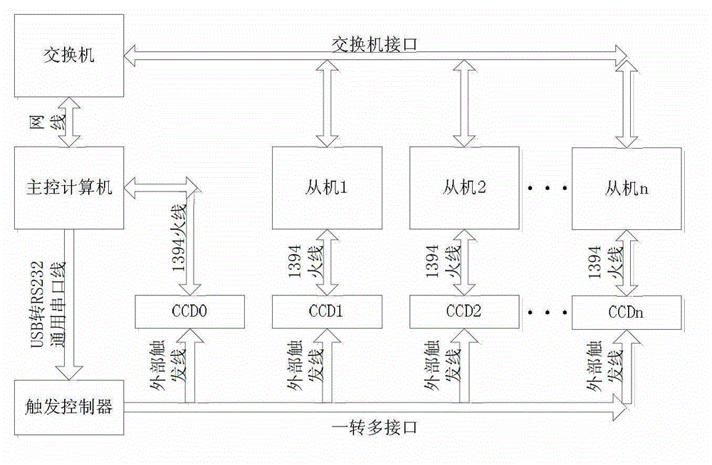
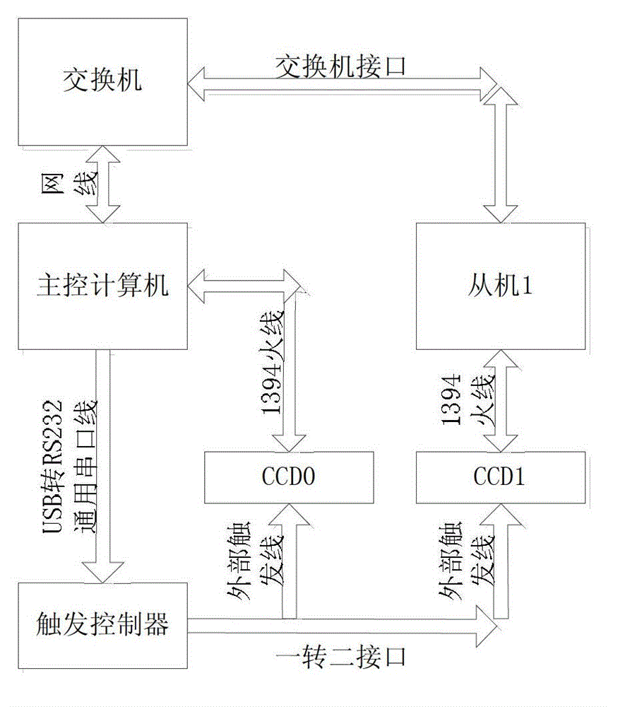
[0033] Such as image 3As shown, this embodiment is a two-way digital camera image acquisition storage device, including a master computer, a slave, two CCD digital cameras, two PCI-E to 1394A interface expansion cards, a switch, a Trigger controller, two RJ45 network cables, one USB to RS232 universal serial port cable, two external trigger cables for CCD digital cameras and two 1394A fire wires. The external trigger wire is a one-to-two-turn wire.
[0034] Specific implementation steps:
[0035] 1. Prepare various components: including a master computer, a slave machine, two CCD digital cameras, two PCI-E to 1394A interface expansion cards, a switch, a trigger controller, two RJ45 network cables, a One USB to TTL data cable, two CCD digital camera external trigger wires and two 1394A fire wires.
[0036] 2. Connect the components: connect the main control computer and the slave to the switch through the RJ45 network cable, connect the trigger controller to the USB type A ...
Embodiment 2
[0045] Such as Figure 4 As shown, this embodiment is a three-way digital camera image acquisition and storage device, including: a master computer, two slave machines, three digital cameras, three PCI-E to 1394A interface expansion cards, a switch, a Trigger controller, three RJ45 network cables, one USB to RS232 universal serial port cable, three external trigger cables of CCD digital camera and three 1394A fire wires. The external trigger wire is a one-to-three-turn connection.
[0046] Refer to the corresponding part in Embodiment 1 for specific implementation steps. Among them, in the second step, connect the components: connect the main control computer and the slave machine to the switch through the RJ45 network cable, connect the trigger controller to the USB type A port of the main control computer through the USB to RS232 universal serial port line, Connect the CCD digital camera to the trigger controller through the external trigger line, insert the PCI-E to 1394A...
PUM
 Abstract
Description
Claims
Application Information
 - R&D
- Intellectual Property
- Life Sciences
- Materials
- Tech Scout
- Unparalleled Data Quality
- Higher Quality Content
- 60% Fewer Hallucinations
Browse by: Latest US Patents, China's latest patents, Technical Efficacy Thesaurus, Application Domain, Technology Topic, Popular Technical Reports.
© 2025 PatSnap. All rights reserved.Legal|Privacy policy|Modern Slavery Act Transparency Statement|Sitemap|About US| Contact US: help@patsnap.com


