
Breaker interlocking mechanism

A circuit breaker and interlocking technology, which is applied in the direction of switchgear, pull-out switchgear, electrical components, etc., can solve the problems of easy loss, unsightly appearance, and high cost, and achieve the effects of reducing carbon dioxide emissions, simplifying the number of parts, and avoiding loss

Inactive Publication Date: 2013-04-24
TIANJIN JIUAN GRP
View PDF5 Cites 1 Cited by
  • Summary
  • Abstract
  • Description
  • Claims
  • Application Information

AI Technical Summary

Problems solved by technology

In the traditional circuit breaker chain mechanism, components such as the lock lever, chain drive plate, lock body and return spring are installed on the handcart through their respective frames. The frames are parts of different shapes that are welded on the handcart to match each component. This kind of circuit breaker interlocking mechanism has the following disadvantages during the installation process: there are many parts that make up the interlocking mechanism, and it is easy to lose during the assembly process; a lot of welding work is required during the installation of the interlocking mechanism, and this process will generate a large amount of carbon dioxide, which is not environmentally friendly. Moreover, the welding process is complicated and the cost is high; the shape of the mechanism is complicated and not beautiful enough

Method used


Image

  • Breaker interlocking mechanism
  • Breaker interlocking mechanism
  • Breaker interlocking mechanism

Examples


Embodiment Construction

[0012] In order to further understand the invention content, characteristics and effects of the present invention, the following examples are given, and detailed descriptions are as follows in conjunction with the accompanying drawings:

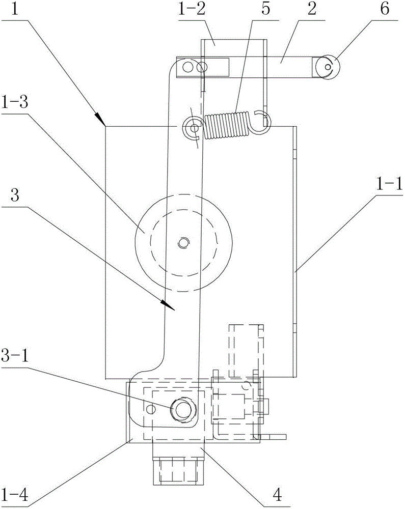
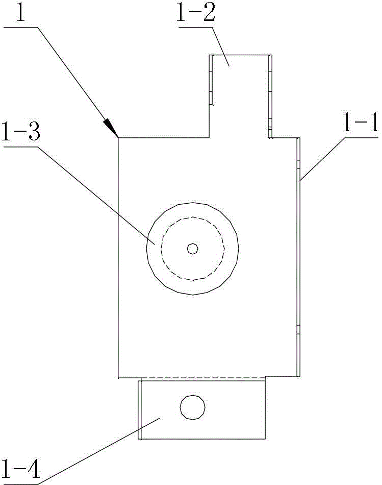
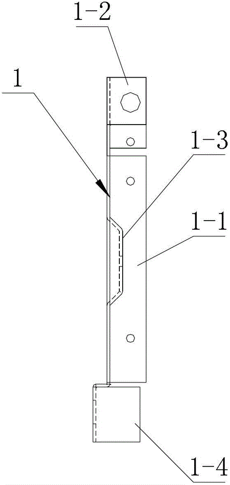
[0013] see Figure 1-Figure 3 , a circuit breaker chain mechanism, including a chain body 1, a lock rod 2, a chain drive plate 3, a lock body 4 and a return spring 5, the chain body 1 is an integrated structure formed by bending a steel plate, and the chain body 1 is a chain mechanism The supporting carrier of each component in it. The chain body 1 has a fixing part 1-1 for connecting with the handcart, and the chain body 1 and the handcart are connected by fasteners. The lock body 1 has a lock rod installation part 1-2 for installing the lock rod 2, that is, the lock rod 2 is movably fitted on the lock rod installation part 1-2, so as to realize the lock rod 2 stretching on the side of the handcart. The interlocking body 1 is provided with...


PUM


Abstract

The invention relates to a breaker interlocking mechanism which comprises a locking rod, a interlocking driver plate, a lock body with a locking dog and a reset spring. One end of the interlocking driver plate is hinged with one end of a locking rod, the other end of the interlocking driver plate is provided with a lock hole matched with the locking dog of the lock body, and the reset spring is connected with the interlocking driver plate. The breaker interlocking mechanism is characterized by comprising a linkage body which is of an integrated structure formed by bending a steel plate, and a fixed portion, a lock rod installing portion, a protruding portion and a lock body fixing portion are arranged on the linkage body, wherein the fixed portion is used for being connected with a handcart, the lock rod installing portion is used for installing the lock rod, the protruding portion is used for being hinged with the interlocking driver plate, the lock body fixing portion is used for installing the lock body, and the reset spring is connected with the lock rod installing portion. The breaker interlocking mechanism has the advantages of being simple in structure, convenient to assemble, low in cost, delicate and attractive in appearance, and low-carbon and environment-friendly in an assembling process.

Description

technical field [0001] The invention belongs to the technical field of power distribution equipment, in particular to a circuit breaker interlocking mechanism. Background technique [0002] The circuit breaker interlocking mechanism is a device used to limit the closing and opening of the circuit breaker synchronously with the push and push of the handcart during the test, maintenance and power transmission of the circuit breaker of the high-voltage switchgear. In the traditional circuit breaker chain mechanism, components such as the lock lever, chain drive plate, lock body and return spring are installed on the handcart through their respective frames. The frames are parts of different shapes that are welded on the handcart to match each component. This kind of circuit breaker interlocking mechanism has the following disadvantages during the installation process: there are many parts that make up the interlocking mechanism, and it is easy to lose during the assembly proces...

Claims


Application Information

Patent Timeline
Patent Type & Authority Applications(China)
IPC IPC(8): H02B11/133
Inventor 李承立杨云鹏韩立功孙立强
Owner TIANJIN JIUAN GRP
Learn More