
A transmission system asynchronous mapping clock recovery method and device

A clock recovery and asynchronous mapping technology, applied in the field of communication transmission system, can solve the problems of difficult filtering of low-frequency jitter, difficult to pass drift index, unacceptable cost, etc., to reduce resources and avoid low-frequency interference.

Active Publication Date: 2017-12-05
ZTE CORP
View PDF4 Cites 0 Cited by
  • Summary
  • Abstract
  • Description
  • Claims
  • Application Information

AI Technical Summary

Problems solved by technology

This method is difficult to filter out the low-frequency jitter introduced during the mapping and demapping process, and the drift index is difficult to pass
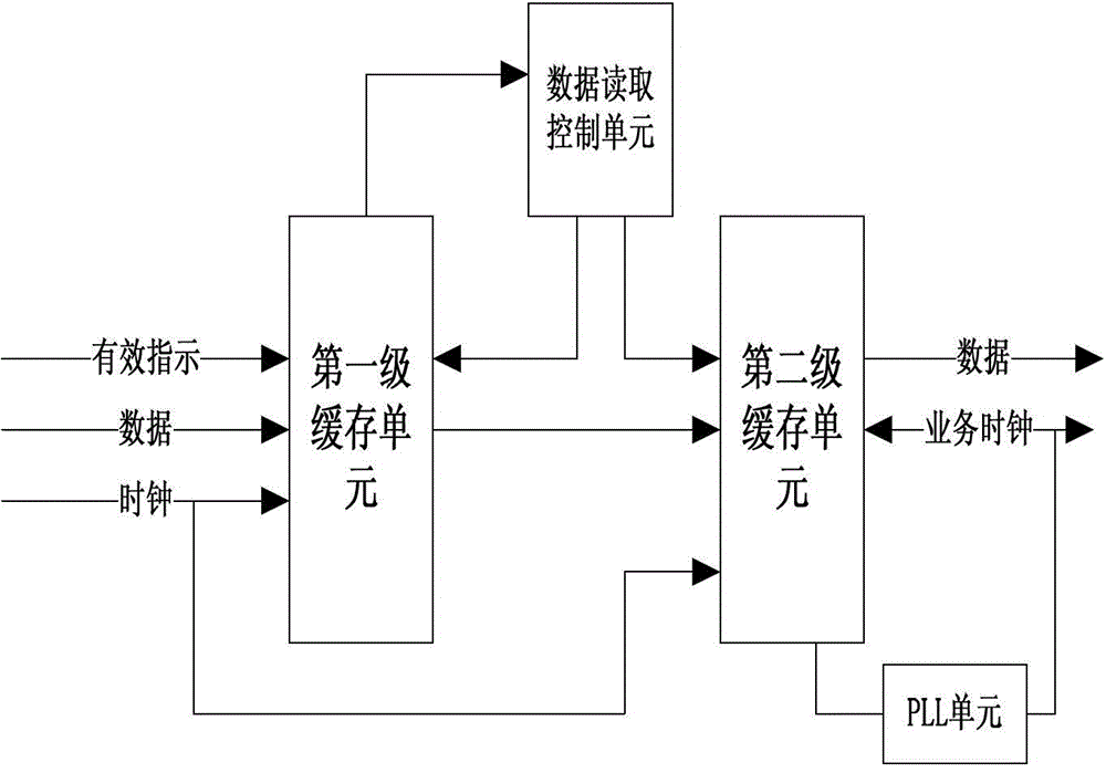
[0009] However, in the face of the transparent transmission requirements of synchronous Ethernet and wireless services, the quality of the clock recovered by using the two-level cache method cannot meet the requirements, and it is difficult to filter out the low-frequency interference introduced during the mapping and demapping process, and the jitter and drift indicators are very low. Difficult to satisfy
If the method of introducing the clock board is adopted, the hardware needs to be redesigned, and many devices on the network need to be updated, which is unacceptable in terms of cost

Method used


Image

  • A transmission system asynchronous mapping clock recovery method and device
  • A transmission system asynchronous mapping clock recovery method and device
  • A transmission system asynchronous mapping clock recovery method and device

Examples


Embodiment Construction

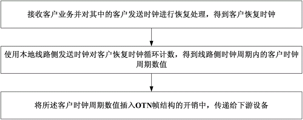
[0036] figure 2 is the transmission system asynchronous mapping clock recovery method of the present invention, such as figure 2 As shown, the transmission system asynchronous mapping clock recovery method of the present invention includes the following steps performed by the upstream device:

[0037] Step A: Receive customer business and recover the customer's sending clock to obtain the customer's recovered clock;

[0038] Step B: Use the sending clock on the local line side to count the client's recovery clock cycle, and obtain the client's clock cycle value within the clock cycle on the line side;

[0039] Step C: insert the client clock cycle value into the overhead of the OTN frame structure, and transmit it to the downstream device.

[0040] The step of obtaining the numerical value of the client clock cycle in the clock cycle of the line side described in step B includes: using the transmission clock of the local line side to carry out self-circulation counting, an...


PUM


Abstract

The present invention relates to a transmission system asynchronous mapping clock recovery method and equipment. The method of the present invention includes: receiving customer service and recovering the customer's transmission clock in it to obtain the customer's recovery clock; using the local line side transmission clock to recover the customer's clock Cycle counting to obtain the client clock cycle value in the clock cycle of the line side; insert the client clock cycle value into the overhead of the OTN frame structure, and transmit it to the downstream device. The beneficial effect of the present invention is that since the clock does not need to be extracted from the service data flow, the difficulty of designing a filter circuit to filter out low-frequency interference is avoided, and the resources occupied by the clock recovery circuit are also greatly reduced.

Description

technical field [0001] The invention relates to the field of communication transmission systems, in particular to a clock recovery method and equipment for asynchronous mapping in an optical transport network. Background technique [0002] With the continuous development of communication technology, OTN has gradually become the mainstream of transmission network, especially the development of OTN-based cross-scheduling technology, which makes OTN gradually develop into a multi-service bearer platform. Many services require transparent transmission of service clocks. [0003] Some services adopt the method of synchronous mapping, that is, the service clock is used to encapsulate the service data flow on the OTN network. This application requires a fixed frequency ratio between the access service and the OTN service, and cannot realize the transparent transmission of multi-channel customer service clocks. [0004] When customer services are transmitted through the OTN networ...

Claims


Application Information

Patent Timeline
Patent Type & Authority Patents(China)
IPC IPC(8): H04J3/16
Inventor 阮景林韦玉线杜凯王春光
Owner ZTE CORP
Learn More