High-pressure discharge lamp having a reference ring, and method for producing the high-pressure discharge lamp

A high-pressure discharge lamp technology, which is applied in the manufacture of discharge tubes/lamps, discharge lamps, electrode systems, etc., can solve the problems of difficulty in accurately maintaining the thickness, increased unit cost, and increased scrap rate.

Inactive Publication Date: 2013-04-24
OSRAM GMBH
View PDF4 Cites 0 Cited by
  • Summary
  • Abstract
  • Description
  • Claims
  • Application Information

AI Technical Summary

Problems solved by technology

In the construction and mounting of reference rings known from the mentioned prior art, it can prove difficult to precisely main

Method used


Image

  • High-pressure discharge lamp having a reference ring, and method for producing the high-pressure discharge lamp
  • High-pressure discharge lamp having a reference ring, and method for producing the high-pressure discharge lamp
  • High-pressure discharge lamp having a reference ring, and method for producing the high-pressure discharge lamp

Examples


Embodiment Construction

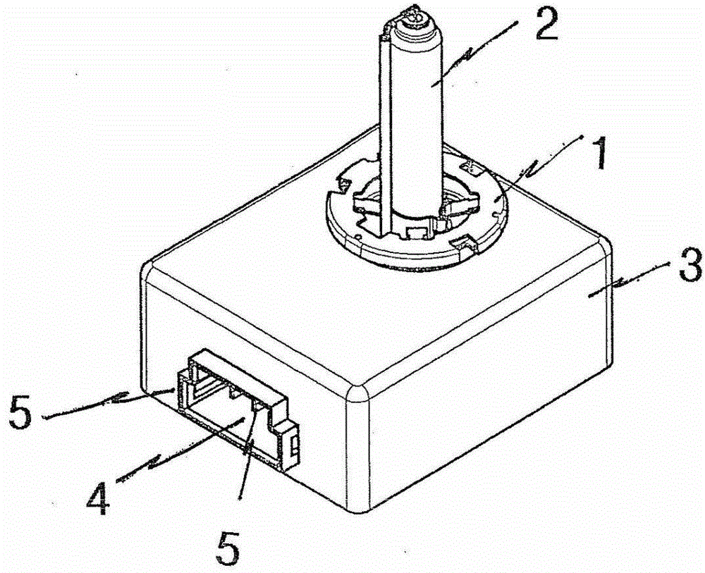
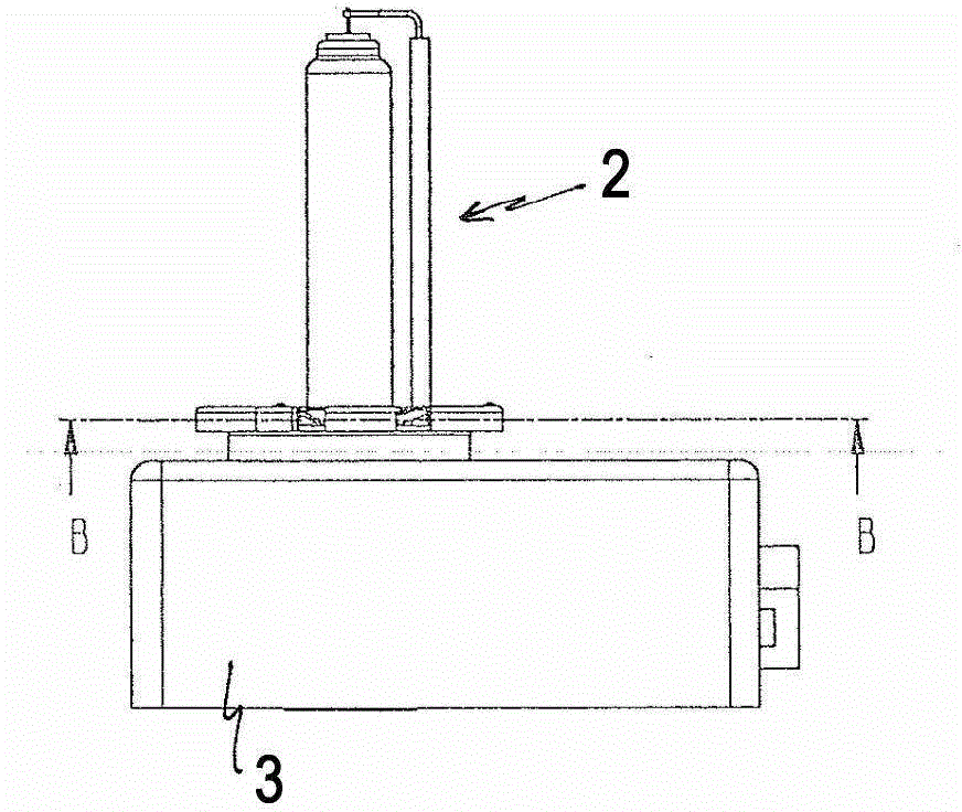
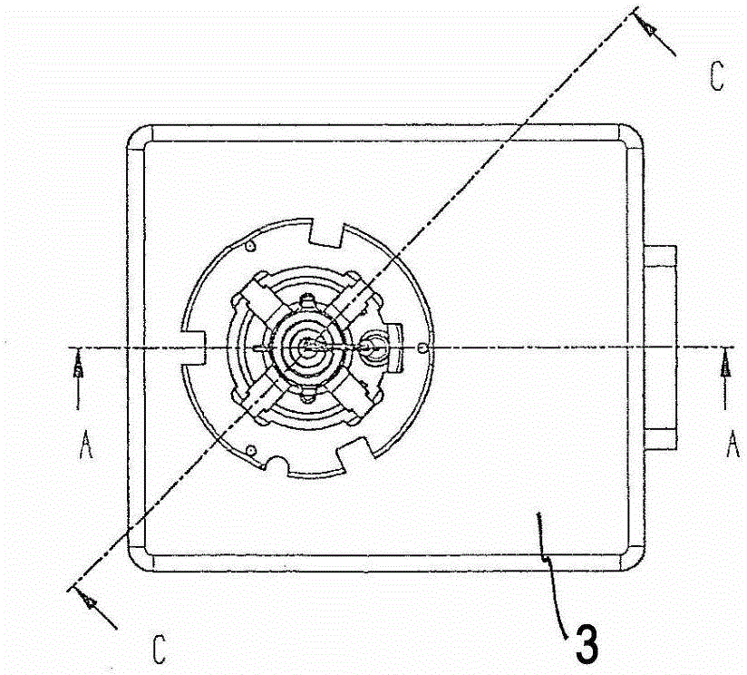
[0030] according to figure 1 , the D lamp of the preferred embodiment of the invention has a metal reference ring 1 in which the burner 2 is firmly fixed in a certain relative position and fixed on the housing 3 of the electronic module not further shown in the figure .

[0031] The housing 3 preferably has the ignition electronics of the D lamp (not shown in the figure) and has connection wells (Anschlussschacht) 4 for the electrical connection of the D lamp to a power supply (not shown in the figure) Contact pin 5 protrudes into it, which as in the figure 1 and Figure 4 shown in .

[0032] The burner 2 comprises a discharge vessel 7 and an outer bulb 6 which surrounds the discharge vessel 7 and is fixed beside the discharge vessel 7. The inner space of the discharge vessel comprises two electrodes arranged opposite each other and xenon gas and a metal halide for generating a gas discharge things. On an end section of the cylindrical outer bulb 6 , a sleeve-like metal b...


PUM


Abstract

The invention discloses a high-pressure discharge lamp (2) having a reference ring (1) comprising a lower ring part, preferably a deep-drawn element, and an upper ring part, preferably a deep-drawn element, on which radially inwardly projecting retaining lugs which are spaced apart in the circumferential direction are formed. According to the invention, the upper and the lower ring part have chamfers which are axially opposite one another (or axially face one another) radially on the outside and have in each case a predefined edge height and which are joined one in the other with surface contact at the periphery and are welded at least in a point-to-point manner on the outer periphery of the chamfer which is situated on the outside as a result.

Description

technical field [0001] The invention proceeds from a high-pressure discharge lamp (hereinafter referred to as D lamp) with an adjusted reference ring according to the preamble of claim 1 . Background technique [0002] WO 2008 / 110969 A2 discloses a high-pressure discharge lamp of this type, which consists of a high-pressure discharge burner on which a sleeve-shaped base is provided, which is inserted into a fixture. For this purpose, the fixture has a ring formed from an inner lower part and an outer upper part, wherein the upper part and the lower part are correspondingly formed (punched / stamped) as deep-drawn parts made of sheet metal and inserted axially into each other and Relatively clamped by the bent part. [0003] The lower inner ring is equipped with four evenly spaced circumferentially axially protruding sockets or projections, through which the inner through-hole of the upper outer ring passes axially through the sockets or projections. The outer ring is clamped...

Claims


Application Information

Patent Timeline
IPC IPC(8): F21V19/00H01J5/60H01J9/34
CPCH01J9/34F21S48/1109H01J5/60
Inventor 卡斯滕·皮奇基利安·克拉格斯
Owner OSRAM GMBH
Why Eureka
Try Eureka