Current collector having built-in sealing means, and bipolar battery including such a collector

一种双极电池、集电体的技术,应用在电极集电体涂层、电极制造、密封材料等方向,能够解决双极电池故障等问题,达到电池有效、改进性能、能量密度大的效果

Inactive Publication Date: 2013-04-24
COMMISSARIAT A LENERGIE ATOMIQUE ET AUX ENERGIES ALTERNATIVES
View PDF19 Cites 18 Cited by
  • Summary
  • Abstract
  • Description
  • Claims
  • Application Information

AI Technical Summary

Problems solved by technology

In fact, poor sealing causes bipolar battery failure

Method used


Image

  • Current collector having built-in sealing means, and bipolar battery including such a collector
  • Current collector having built-in sealing means, and bipolar battery including such a collector
  • Current collector having built-in sealing means, and bipolar battery including such a collector

Examples


Embodiment Construction

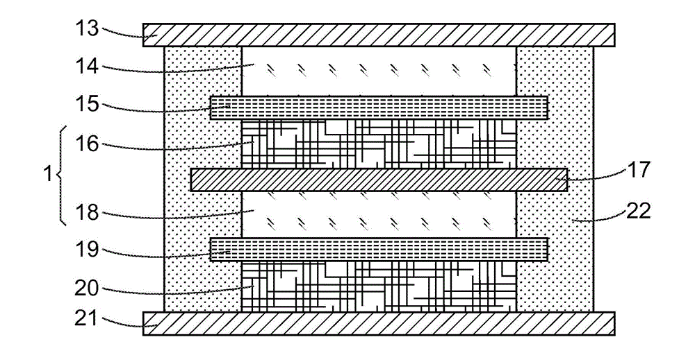
[0080]exist figure 1 A Li-ion bipolar battery according to the prior art is presented in , as it is set forth in patent application WO03 / 047021.

[0081] This battery comprises in its upper part a conductive aluminum substrate (substrate, base material) 13 (positive terminal current collector) and is composed of a positive lithium intercalation material such as Li 1.04 mn 1.96 o 4 The fabricated active layer 14, and in its lower part comprises a conductive aluminum substrate 21 (the negative terminal current collector) and is composed of a positive lithium intercalation material such as Li 4 Ti 5 o 12 Fabricated active layer 20.

[0082] In this cell, a bipolar electrode 1 , also called a bipolar current collector, comprises a positive active layer 18 and a negative active layer 19 on either side of a conductive aluminum substrate 17 in the form of a plate.

[0083] The lower electrode 20 and the upper electrode 14 are separated from the bipolar electrode 1 by two separa...


PUM

PropertyMeasurementUnit
lengthaaaaaaaaaa

Abstract

The invention relates to bipolar lithium batteries. In order to improve the seal with respect to the electrolytes between adjacent electrochemical cells, the invention involves producing novel mixed electrode-supporting current collectors (10), in the form of a metal grate (101) or a raised metal sheet accommodated in a strip (100) made of an electrically insulating material, the periphery (100p) of which has the function of forming the sealing area.

Description

technical field [0001] The invention relates to the field of lithium electrochemical generators, which operate according to the intercalation (intercalation) or deintercalation, or in other words intercalation-deintercalation principle, of lithium in at least one electrode. [0002] More specifically, it relates to lithium electrochemical accumulators comprising at least one current collector (current collector, current collector) having a bipolar function, also known as bipolar cells: in such bipolar cells, in a Each opposing face of the electrode material supports a bipolar current collector, eg, having a cathode (positive electrode) supported by one face and an anode (negative electrode) supported by the other opposing face. [0003] The object of the present invention is to improve the sealing of electrochemical generators against electrolytes and, in particular, of bipolar cells against electrolytes in liquid form. Background technique [0004] The configuration of a c...

Claims


Application Information

Patent Timeline
Patent Type & Authority Applications(China)
IPC IPC(8): H01M2/26H01M4/58H01M4/66H01M4/74H01M4/04H01M10/0525H01M4/485H01M50/184H01M50/186
CPCH01M4/5825H01M4/667H01M4/66H01M2/26H01M10/0585H01M10/0525H01M4/0435H01M2/08H01M4/043H01M4/0404H01M4/485H01M4/745Y02E60/122H01M4/668H01M4/661H01M4/72H01M6/005H01M4/136H01M4/131Y10T29/4911Y02P70/50Y02E60/10H01M50/184H01M50/186H01M50/531
Inventor 玛丽安娜·沙米
Owner COMMISSARIAT A LENERGIE ATOMIQUE ET AUX ENERGIES ALTERNATIVES
Why Eureka
Try Eureka