Laser cutting head follow-up device

A technology of laser cutting head and follow-up device, applied in laser welding equipment, welding equipment, metal processing equipment, etc., can solve the problems of difficult assembly, inflexible movement of nozzle up and down, slow response, etc., to achieve consistent cutting and forming, improve cutting Quality and cutting efficiency, good anti-loosening effect

Inactive Publication Date: 2013-05-01
浪潮数字(山东)科技有限公司
View PDF7 Cites 10 Cited by
  • Summary
  • Abstract
  • Description
  • Claims
  • Application Information

AI Technical Summary

Problems solved by technology

In this structure, the ball screw only plays a driving role. It is difficult to ensure the distance and parallelism between the ball screw and the two circular guide rails at the same time. Usually, the bearing position of the ball screw or the guide rod shaft end can be adjusted, that is, Bearing seats 1 and 8 need to be adjusted up and down, the structure is complicated, assembly is difficult, the nozzle moves up and down flexibly, and the response is slow

Method used


Image

  • Laser cutting head follow-up device
  • Laser cutting head follow-up device
  • Laser cutting head follow-up device

Examples


Embodiment Construction

[0011] The present invention is described in detail below in conjunction with accompanying drawing

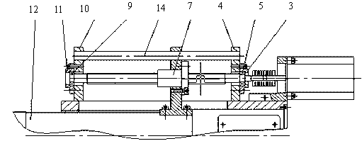
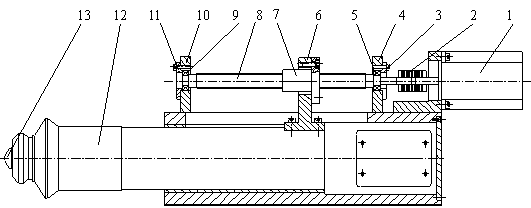
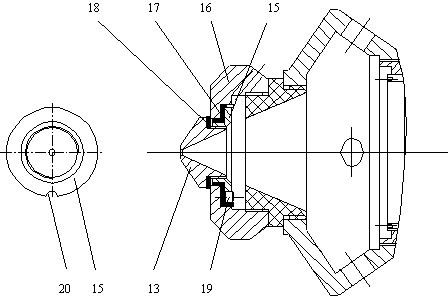
[0012] See attached figure 2 , image 3 , a laser cutting head servo device, including a stepping motor 1, a coupling 2, a bearing seat 3, a shaft end support 4, a rolling bearing 5, a nut seat 6, a ball screw nut 7, and a ball screw 8 , Rolling bearing two 9, shaft end support two 10, bearing seat two 11, sleeve 12, nozzle 13, the stepping motor 1 is connected with the ball screw 8 through the coupling 2, rolling bearing one 5 is through the shaft end support one 4 It is fixed on bearing seat 1 3, rolling bearing 2 9 is fixed on bearing seat 2 11 through shaft end support 2 10, said rolling bearing 1 5 and rolling bearing 2 9 are connected by ball screw 8, nut seat 6 and ball screw nut 7 The end faces are matched, and there is a gap in the radial direction. The front end of the sleeve 12 is provided with a nozzle 13. The nozzle 13 is isolated from the outside world through ...


PUM


Abstract

The present invention belongs to the technical field of laser machining equipment, and particularly relates to a laser cutting head follow-up device. The laser cutting head follow-up device comprises a stepping motor, a coupling, a bearing seat I, a shaft end support I, a rolling bearing I, a nut seat, a ball screw nut, a ball screw, a rolling bearing II, a shaft end support II, a bearing seat II, a sleeve and a nozzle. The laser cutting head follow-up device has the advantages that a guide rail is reduced, the ball screw simultaneously has the effects of transmission and guiding, a half-arc groove milled on the excircle of the nut is matched with a cylindrical pin and has good anti-loose effect, capacitive sensing is adopted, the rotation of the stepping motor is controlled through electric signals, the distance between the laser nozzle and the surface of a cut work piece can be automatically adjusted, automatic focusing is always performed, work pieces are artistic, uniformly cut and formed, and have no burrs, and the cutting quality and the cutting efficiency are greatly improved.

Description

technical field [0001] The invention belongs to the technical field of laser processing equipment, and in particular relates to a laser cutting head follower. Background technique [0002] In laser cutting, the distance between the nozzle and the surface of the workpiece to be cut is one of the main factors that determine the quality of the cut and the cutting speed. During cutting, the height from the nozzle to the surface of the workpiece to be cut must be kept stable and consistent. The traditional laser cutting head only has focusing lens and nozzle, and has no auto-focus function. During large-format laser cutting, especially when cutting thin plates and materials with low surface flatness, the height from the nozzle to the surface of the cut workpiece varies from place to place. Due to the difference, the surface of the material to be cut deviates from the focal length, the size of the focus spot is different, and the power density is also different, resulting in i...

Claims


Application Information

Patent Timeline
Patent Type & Authority Applications(China)
IPC IPC(8): B23K26/38B23K26/08B23K26/046
Inventor 尚勇高凯侯志坚陈传明张维勇董玲
Owner 浪潮数字(山东)科技有限公司
Why Eureka
Try Eureka