Signal lamp

A signal lamp and housing technology, which is applied in the field of signal lamps to achieve the effect of preventing scattering

Inactive Publication Date: 2013-05-01
张桓毓
View PDF11 Cites 0 Cited by
  • Summary
  • Abstract
  • Description
  • Claims
  • Application Information

AI Technical Summary

Problems solved by technology

However, the design of the existing LED signal lights on the angle of light irradiation needs to be further optimized

Method used


Image

  • Signal lamp

Examples


Embodiment Construction

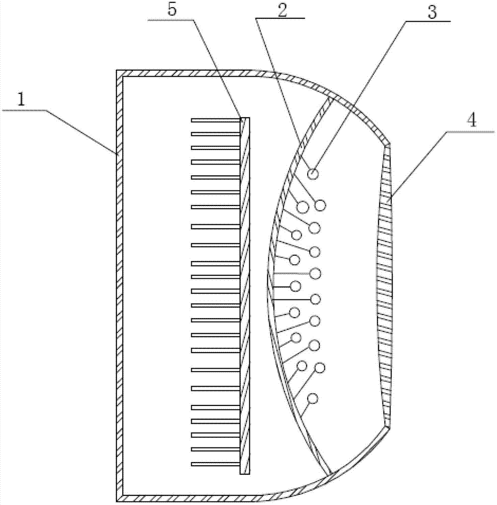
[0018] Such as figure 1 As shown, a signal lamp of the present invention includes a cavity housing 1 with an open front end, a mounting plate 2 and an array of LED light-emitting diodes 3 arranged on the mounting plate 2, and the internal front end of the housing 1 is provided with a mounting plate 2 , the upper and lower inner walls of the front end of the housing 1 have a symmetrical arc structure, and the best is that the central angles subtended by the upper and lower inner walls of the front end of the housing 1 are all 30° to 90°.

[0019] A condenser lens 4 is provided on the opening, and the condenser lens 4 is sealed and connected with the housing 1. The condenser lens 4 plays the role of converging light, so that the emitted light of the LED light-emitting diode 3 of the LED light-emitting diode 3 is emitted along the front , to increase the intensity of light irradiation. At the joint between the condenser lens 4 and the housing 1 , a waterproof sealing lamination ...


PUM


Abstract

The invention discloses a signal lamp which comprises a hollow shell, a mounting plate and an LED (Light Emitting Diode) array, wherein an opening is formed in the front end of the hollow shell; the LED array is arranged on the mounting plate which is arranged on the front end of the inner part of the shell; the upper and lower inner walls of the front end of the shell form a symmetrical cambered-surface structure; and a collecting lens is arranged on the opening and is in seal connection with the shell. The upper and lower inner walls of the front end of the shell form the symmetrical cambered surface structure, so that light emitted by LEDs of the LED array can be prevented from diffusing outside the shell, so as not cause side transmitting light which can influence moving vehicles to judge the signal lamp.

Description

technical field [0001] The invention relates to the technical field of signal lamps, in particular to a signal lamp using LEDs as light sources. Background technique [0002] Road traffic signal lights are a category of traffic safety products. They are an important tool to strengthen road traffic management, reduce traffic accidents, improve road use efficiency, and improve traffic conditions. Applicable to intersections such as crosses and T-shaped intersections, it is controlled by road traffic signal controllers to guide vehicles and pedestrians to pass safely and orderly. The light intensity and irradiation angle of the signal light directly affect the running state of road traffic. If the irradiation angle of the signal light is too large, it will mislead vehicles in different driving directions. For example, in the design of signal lights, if the irradiation angle is too large, it will aggravate the misleading of vehicles in different driving directions to the signal...

Claims


Application Information

Patent Timeline
Patent Type & Authority Applications(China)
IPC IPC(8): G08G1/095F21V5/04F21W111/02F21Y101/02
Inventor 张桓毓
Owner 张桓毓
Why Eureka
Try Eureka