Display device and method for on-load testing of display device

A display device and display panel technology, which is applied to static indicators, instruments, etc., can solve the problems of affecting the accuracy of mass-produced codes, and achieve the effect of improving accuracy

Active Publication Date: 2020-10-13
TCL CHINA STAR OPTOELECTRONICS TECH CO LTD
View PDF9 Cites 0 Cited by
  • Summary
  • Abstract
  • Description
  • Claims
  • Application Information

AI Technical Summary

Problems solved by technology

[0005] The purpose of this application is to provide a display device and a method for on-load testing of the display device, so as to solve the problem that the accuracy judgment of the mass-produced code is affected due to signal attenuation during the on-load test

Method used


Image

  • Display device and method for on-load testing of display device
  • Display device and method for on-load testing of display device

Examples


Embodiment Construction

[0035] The technical solutions in the embodiments of the present application will be clearly and completely described below in conjunction with the drawings in the embodiments of the present application. Apparently, the described embodiments are only some of the embodiments of this application, not all of them. Based on the embodiments in this application, all other embodiments obtained by those skilled in the art without making creative efforts belong to the scope of protection of this application.

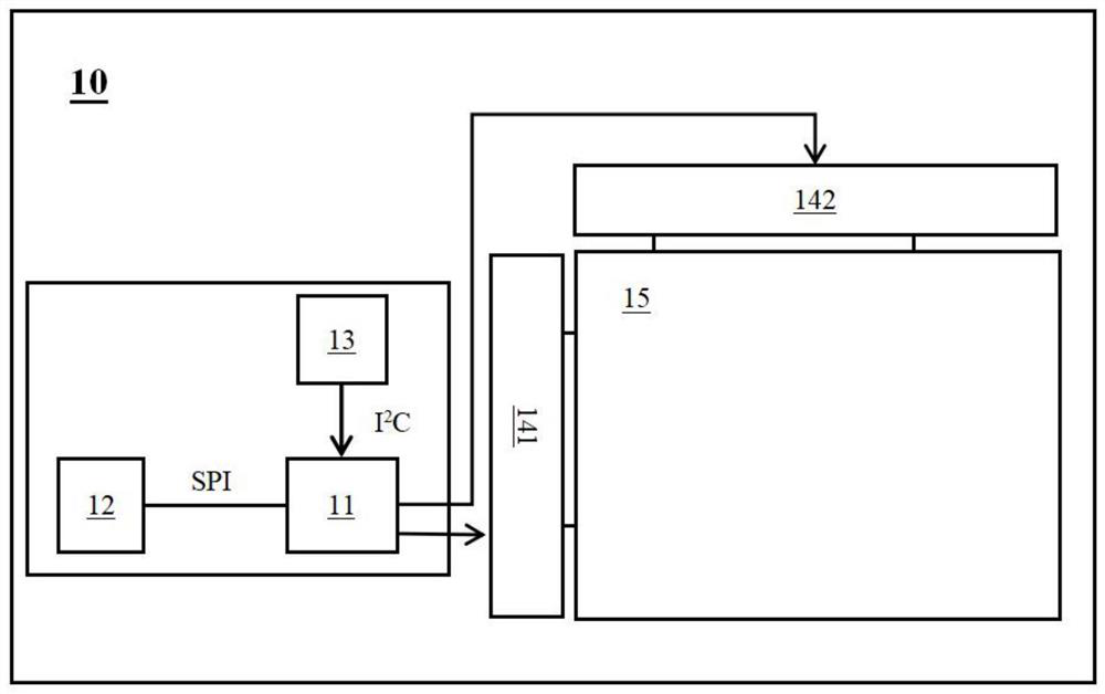
[0036] see figure 1 , which is a display device 10 according to an embodiment of the present application. The display device 10 includes a timing controller 11, a flash memory chip 12, a driver chip 14, an internal integrated circuit bus controller 13, and a display panel 15. The timing controller 11 and the flash memory chip 12 , driver chip 14 and internal integrated circuit bus controller (I 2 C-bus Control, Inter-Integrated Circuit Bus Control) 13 connection, the display pa...


PUM


Abstract

A display device (10) and a display device (10) load testing method. By means of a timing controller (11) receiving and executing an eye pattern enlarging instruction output by an inner integrated circuit bus controller (13) to correspondingly output an eye pattern enlarging drive signal to a driving chip (14), influence on the determination of a load testing result due to the serious attenuation of a drive signal during the load testing of the display device (10) is avoided, thereby improving the accuracy of the load testing of the display device (10).

Description

technical field [0001] The present application relates to the field of display technology, in particular to a display device and a method for on-load testing of the display device. Background technique [0002] After the display device is manufactured, it is necessary to judge the accuracy of the mass production code burned in the flash memory of the printed circuit board (Printed Circuit Board Assembly, PCBA). The mass production code includes various control circuits (sequence control circuit, programmable gamma correction buffer circuit and digital power management integrated circuit, etc.) data information required for operation. When judging the mass production code, it is necessary to use a jumper to transmit the test signal output by the test equipment to the control circuit on the printed circuit board for processing, and the control circuit needs to run the mass production code to be in a working state to process the test signal. The final test signal is transmitte...

Claims


Application Information

Patent Timeline
Patent Type & Authority Patents(China)
IPC IPC(8): G09G3/00
CPCG09G3/006
Inventor 李继龙王月
Owner TCL CHINA STAR OPTOELECTRONICS TECH CO LTD
Why Eureka
Try Eureka