Loop Elimination Method and Device Applied in Resilient Packet Ring Network
A resilient packet ring and loop technology, applied in the field of network communication, can solve problems such as data packet forwarding storms and implementation complexity
- Summary
- Abstract
- Description
- Claims
- Application Information
AI Technical Summary
Problems solved by technology
Method used
Image
Examples
Embodiment 1
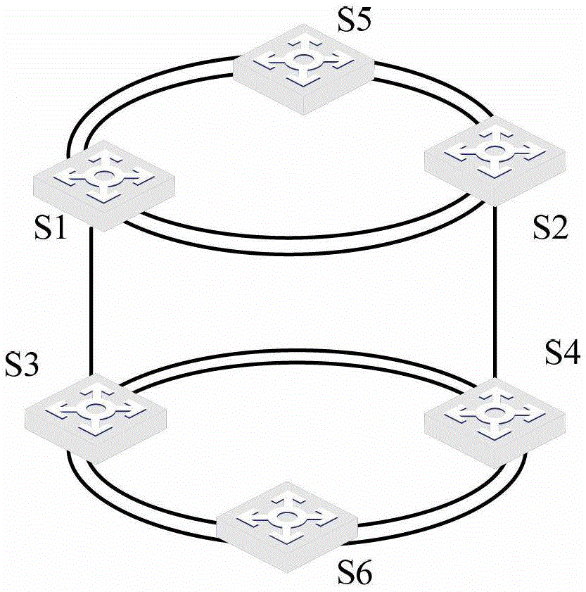
[0122] In the RPR network provided in Embodiment 1, different RPRs can be bridged through Ethernet. see Figure 5 , Figure 5 A schematic diagram of an RPR network applied in Embodiment 1 of the present invention is shown. exist Figure 5 In the RPR network, RPR1 and RPR2 exist in the RPR network, where the abstraction of RPR1 is equivalent to Figure 5 The shown HUB1, S1, S4, and S5 are nodes on RPR1, which are respectively connected to HUB1 through the local RPR logical port, and the abstraction of RPR2 is equivalent to Figure 5 The shown HUB2, S2, S3, and S6 are nodes on RPR2, which are respectively connected to HUB2 through local RPR logical ports; and, in Figure 5 Among them, nodes S1, S4 on RPR1 and nodes S2, S3 on RPR2 are bridged through Ethernet, specifically as Figure 5 shown.
[0123] based on Figure 5 As shown in the RPR network, it can be seen that the loops in the entire RPR network include not only RPR1 and RPR2, but also a loop between nodes S1 and S...
Embodiment 2
[0125] So far, the description of Embodiment 1 is completed. Embodiment 2 is described below:
[0126] Example 2:
[0127] In the RPR network provided in Embodiment 2, different RPRs intersect. see Figure 6 , Figure 6 A schematic diagram of an RPR network applied in Embodiment 2 of the present invention is shown. exist Figure 6 In the RPR network, RPR1 and RPR2 exist in the RPR network, where the abstraction of RPR1 is equivalent to Figure 6 The shown HUB1, S1, S4, and S5 are nodes on RPR1, which are respectively connected to HUB1 through the local RPR logical port, and the abstraction of RPR2 is equivalent to Figure 6 The shown HUB2, S1, S4, and S6 are nodes on RPR2, which are respectively connected to HUB2 through local RPR logical ports; Figure 6 , RPR1 and RPR2 intersect, and the intersection points of the two are S1 and S4, specifically as Figure 6 shown.
[0128] based on Figure 6 As shown in the RPR network, it can be seen that the loops in the entire ...
Embodiment 3
[0132] In the RPR network provided in Embodiment 3, there is an Ethernet bridge between at least two nodes on the same RPR, specifically as Figure 7 shown. see Figure 7 , Figure 7 A schematic diagram of an RPR network applied in Embodiment 3 of the present invention is shown. exist Figure 7 Among them, one RPR in the RPR network (the abstract equivalent is HUB1), the nodes S1 and S2 on it are connected not only through the RPR, but also through the Ethernet port.
[0133] based on Figure 7 As shown in the RPR network, it can be seen that the loops in the entire RPR network include not only the RPR, but also a loop (called an intergroup loop) between nodes S1 and S2 on RPR1, such as Figure 7 As shown, the intergroup ring is composed of rpr1 of S1, HUB1, rpr2 of S2, G1 / 0 / 4 of S2, and G1 / 0 / 1 of S1. For this situation, if the nodes in the entire RPR network forward packets according to the existing RPR standard, the packet forwarding storm will be caused by the inter-g...
PUM
 Abstract
Description
Claims
Application Information
 - R&D
- Intellectual Property
- Life Sciences
- Materials
- Tech Scout
- Unparalleled Data Quality
- Higher Quality Content
- 60% Fewer Hallucinations
Browse by: Latest US Patents, China's latest patents, Technical Efficacy Thesaurus, Application Domain, Technology Topic, Popular Technical Reports.
© 2025 PatSnap. All rights reserved.Legal|Privacy policy|Modern Slavery Act Transparency Statement|Sitemap|About US| Contact US: help@patsnap.com


