Compacting device

A tool and component technology, applied in the field of compaction tools, can solve the problems of mold tool forming force/deformation force limitation, insufficient surface compaction, mold tool stability and low wear resistance, etc.

Inactive Publication Date: 2013-05-01
MIBA SINTER AUSTRIA
View PDF6 Cites 2 Cited by
  • Summary
  • Abstract
  • Description
  • Claims
  • Application Information

AI Technical Summary

Problems solved by technology

But the shortcoming of the method described in the US-B1 document or the female mold tool is that: due to the design of an intermediate cavity between each female template, the stability and wear resistance of the female mold tool are relatively small, thus making the Forming / deformation forces that can be accommodated by the female tool are significantly limited and the achievable surface compaction is not sufficient for some applications

Method used


Image

  • Compacting device
  • Compacting device
  • Compacting device

Examples


Embodiment Construction

[0024] First of all, it should be noted that when describing different embodiments, the same components / parts are provided with the same reference numerals or the same component names, wherein the disclosure content contained in all the descriptions of the specification can be transferred in a meaningful way. For components / parts that are provided with the same reference number or with the same component designation. Furthermore, the position description words (such as up, down, side, etc.) used in the description of the specification are all for the directly described and represented drawings, and they can be transferred to new location. In addition, individual features or combinations of features resulting from the various exemplary embodiments shown and described can themselves form individual solutions according to the invention.

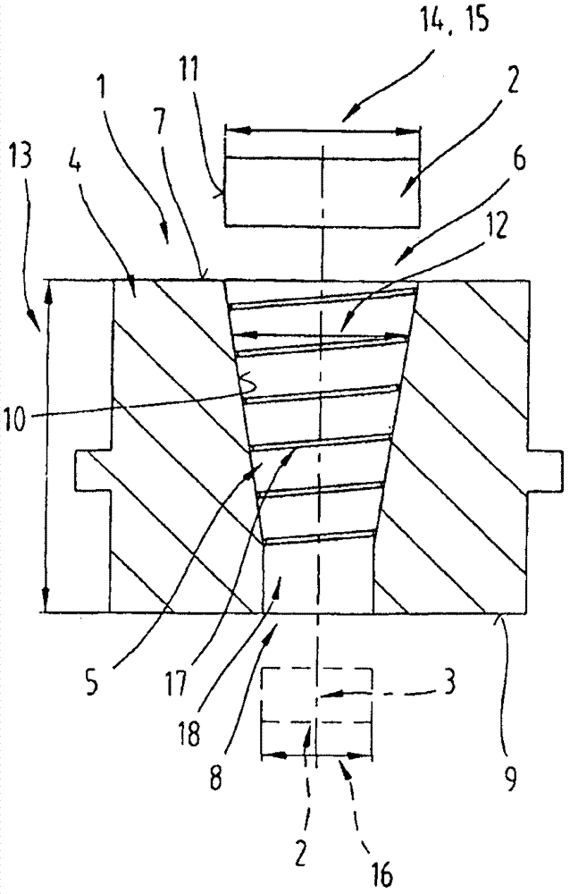
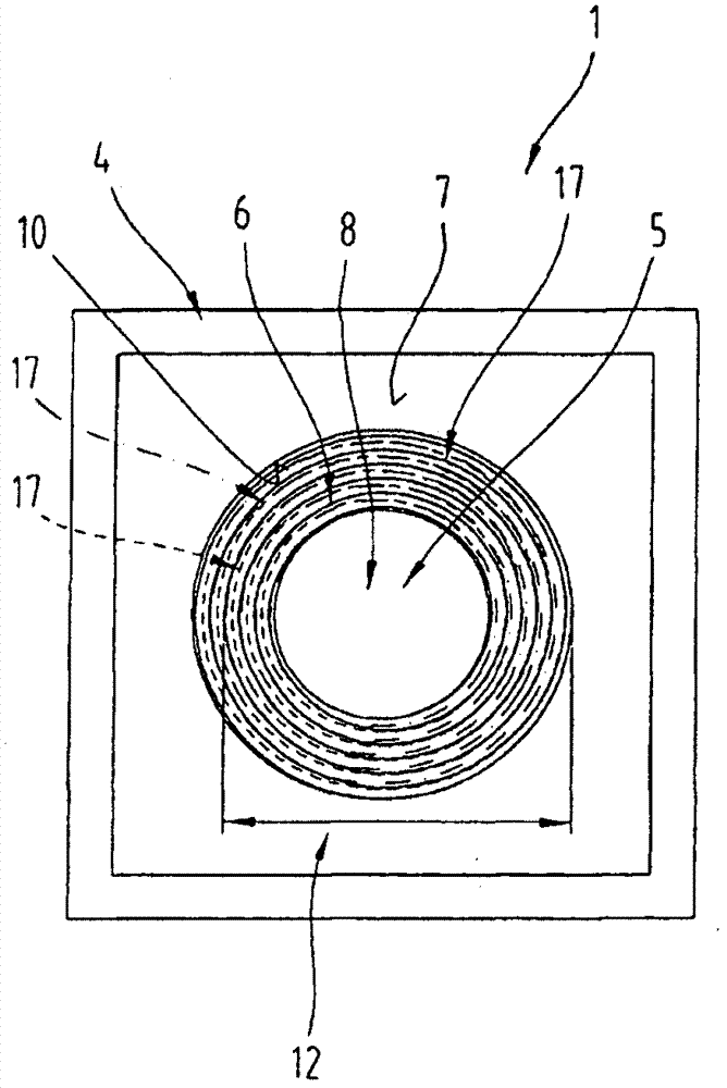
[0025] attached figure 1 with 2 A longitudinal section and a top view are shown of a die 1 for a tool to compact the surface of a component ...


PUM


Abstract

The invention relates to a tool for compacting the surface of a powder-metallurgically produced component (2), comprising a female die (1) and a male die (20), a clearance (5) which extends from a first female die opening (6) to a second female die opening (8) being arranged in the female die (1) and having a wall surface (10) for bearing against the component (2), and the male die (20) having a male die length (23) and a male die surface (21), wherein an inside diameter (12) of the clearance (5) in the female die (1) becomes smaller from the first female die opening (6) in the direction of the second female die opening (8) or an outside diameter (22) of the male die (20) becomes greater over the male die length (23), and wherein a compacting element (17) is arranged on the wall surface (10) of the female die (1) or on the male die surface (21). The compacting element (17) is formed with a thread-like profile.

Description

technical field [0001] The invention relates to a tool for compacting the surface of a component made by powder metallurgy, comprising a female mold and a male mold, wherein a void is provided in the female mold, and the void is formed from a first female mold The die opening extends to the second female die opening and the void has a wall surface in contact with the component, the male die has a male die length and a male die surface, and the inner diameter of the void portion of the female die extends from the first female die port toward The opening of the second female die becomes smaller, or the outer diameter of the male die becomes larger in the length of the male die, and a compacting element is arranged on the wall of the female die or on the surface of the male die; the present invention It also relates to a method for compacting the surface of a component manufactured by powder metallurgy by means of a tool having a die and a die, wherein the die is moved through th...

Claims


Application Information

Patent Timeline
Patent Type & Authority Applications(China)
IPC IPC(8): B22F3/16
CPCB22F3/24B22F3/03
Inventor C·杜曼斯基R·施皮塔勒
Owner MIBA SINTER AUSTRIA
Why Eureka
Try Eureka