
Punching shear punch capable of automatically changing tools

A technology for automatic tool changing and punching machine, applied in the field of punching and shearing punching machines, can solve the problem of low efficiency of manual tool replacement, save labor, shorten tool changing time, and improve production efficiency.

Inactive Publication Date: 2013-05-08
佛山市诺创智能设备有限公司
View PDF7 Cites 5 Cited by
  • Summary
  • Abstract
  • Description
  • Claims
  • Application Information

AI Technical Summary

Problems solved by technology

[0004] The invention provides a punching and shearing punching machine capable of quickly changing knives, which realizes automatic changing of knives and solves the problem of low efficiency of manual changing of knives

Method used


Image

  • Punching shear punch capable of automatically changing tools
  • Punching shear punch capable of automatically changing tools
  • Punching shear punch capable of automatically changing tools

Examples


Embodiment 1

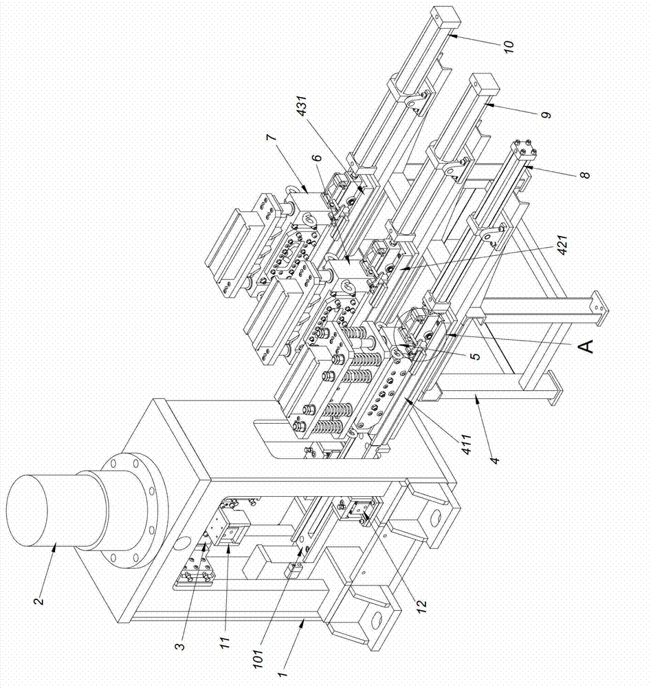
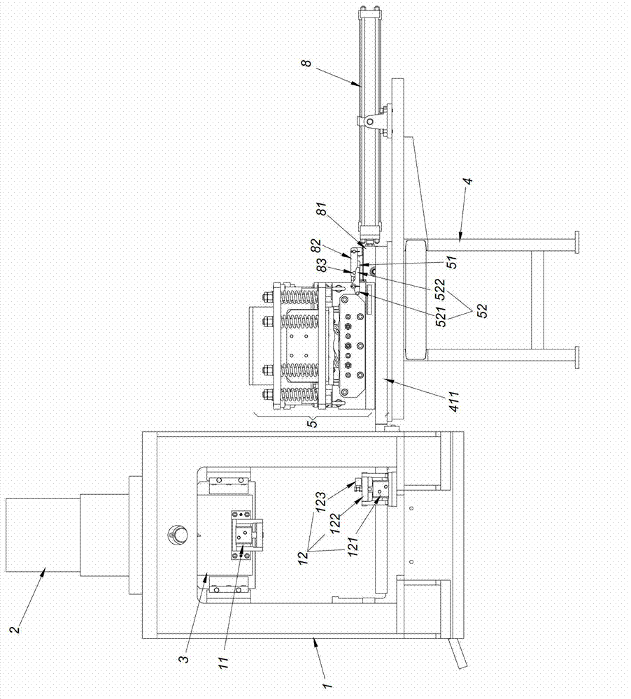
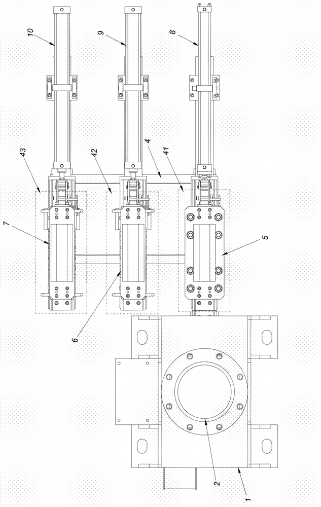
[0028] Such as figure 1 , figure 2 , image 3 As shown, the punching and shearing punching machine of this embodiment includes: a main frame 1, a main hydraulic cylinder 2 as a reciprocating power device, a moving knife connecting seat 3, a tool holder 4, a first tool combination 5, a second tool combination 6, a second tool combination Three knife combination 7, the first push-pull cylinder 8, the second push-pull cylinder 9 and the third push-pull cylinder 10. The first knife assembly 5, the second knife assembly 6, the third knife assembly 7 each comprise an upper knife and a lower knife.

[0029] A guide groove is provided between the movable knife connecting seat 3 and the main frame 1, so the movable knife connecting seat 3 can only move linearly along the vertical direction. The moving knife connecting seat 3 is driven by the main hydraulic cylinder 2. A movable knife clamping cylinder device 11 as a movable knife locking device is provided on the movable knife con...

Embodiment 2

[0038] Tool rest is arranged on the side of main frame among the embodiment 1. Such as Figure 5 As shown, the difference between this embodiment and Embodiment 1 is that the tool rack is divided into a first tool rack 401' and a second tool rack 402', and the first tool rack 401' and the second tool rack 402' are arranged on the host Rack 1' on both sides. The first tool rack 401' is provided with a first placement position 41' and a second placement position 42', and the second tool rack 402' is provided with a third placement position 43', a fourth placement position 44' and a fifth placement position. Stands 45'. Such a layout can shorten the moving distance of the main frame along the conveying direction of the production line and save the length of the production line when there are many tool combinations available.


PUM


Abstract

The invention provides a punching shear punch capable of automatically changing tools. The punching shear punch capable of automatically changing the tools comprises a main rack, a reciprocating power device and a moving tool connecting seat. Particularly, a moving tool locking device is arranged on the moving tool connecting seat, and a static tool locking device is arranged on the main rack. The punching shear punch capable of automatically changing the tools further comprises tool rests and at least two tool assemblies, wherein the tool rests are arranged on one side or two sides of the main rack, the tool rests are provided with placing positions, the number of the placing positions are no smaller than that of the tool assemblies, and each placing position corresponds to a push-pull device. The tool assemblies stay on the main rack or the placing positions of tool rests, and a push-out head and a clasp piece capable of swinging relative to the push-out head are installed on a moving part of each push-pull device. Each tool assembly comprises an upper tool and a lower tool, each lower tool is provided with a drag hook, a tappet capable of rotating relative to the drag hook is arranged beside the drag hook, one end of the tappet is a transmission end, the other end of the tappet is a unclasping end, and the transmission end of the tappet and the static tool locking device are in a linkage. The punching shear punch capable of automatically changing the tools is short in tool changing time and can effectively promote the manufacturing efficiency.

Description

technical field [0001] The invention relates to a punching and shearing press machine on a production line, in particular to a punching and shearing punching machine capable of automatic tool replacement. Background technique [0002] Punching and Shearing A punching machine is a shearing or punching device on a roller line that, depending on the tool installed, can be used to cut the sheet to the required length or to emboss the sheet. In a modern flexible production line, a roller line often needs to produce 2 or 3 specifications of profiles, and generally the profile specifications need to be changed once every 1 to 2 days. In this way, the tools on the punching and shearing presses need to be replaced frequently. The knives on the punching and shearing press are divided into static knives and moving knives, and the static knives and moving knives are used together. Before work, the punching, shearing and punching machine can move back and forth along the conveying direc...

Claims


Application Information

Patent Timeline
Patent Type & Authority Applications(China)
IPC IPC(8): B23D27/00B23Q3/155
Inventor 梁维李明富李伟刘阿缔
Owner 佛山市诺创智能设备有限公司
Learn More