A driving and guiding mechanism of a numerical control cutting machine

A guiding mechanism and cutting machine technology, applied in metal processing and other directions, can solve problems such as the reduction of the life of the rack and pinion, the poor meshing of the rack and pinion, and the easy vibration of the bracket, so as to prolong the service life, ensure cutting accuracy, and prevent jamming. effect of death

Active Publication Date: 2015-08-12
山东艾西特数控机械有限公司
View PDF6 Cites 0 Cited by
  • Summary
  • Abstract
  • Description
  • Claims
  • Application Information

AI Technical Summary

Problems solved by technology

[0002] In the prior art, the well-known technology is that the drive guide mechanism support of the CNC cutting machine used now is a cantilever structure, and the lower part of the support is provided with racks and gears to realize the forward or backward movement of the cantilever mechanism. During use, the support is easy Deformation will lead to poor meshing of the rack and pinion, which will reduce the life of the rack and pinion. Moreover, when the support is running at high speed or under heavy load, the support is prone to vibration and gaps will be generated, resulting in poor running stability and reduced machine tool accuracy. There are deficiencies in the technology

Method used


Image

  • A driving and guiding mechanism of a numerical control cutting machine
  • A driving and guiding mechanism of a numerical control cutting machine
  • A driving and guiding mechanism of a numerical control cutting machine

Examples


Embodiment Construction

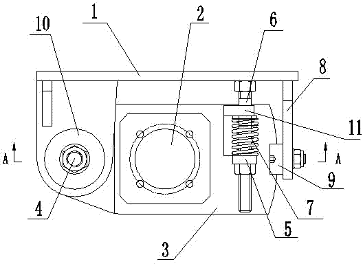
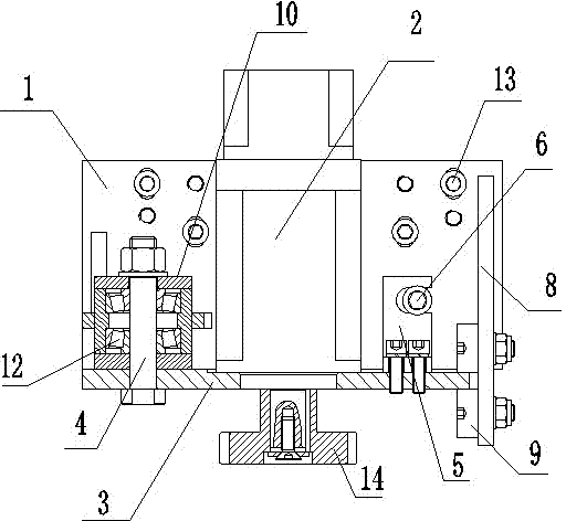
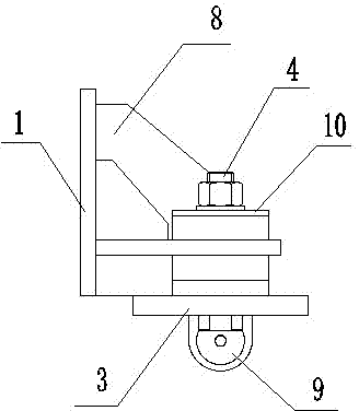
[0011] In order to clearly illustrate the technical features of the solution, the solution will be described below through a specific implementation mode combined with the accompanying drawings.

[0012] It can be seen from the accompanying drawings that the driving and guiding mechanism of the CNC cutting machine of this program includes a connecting plate 1, and the connecting plate 1 is provided with a supporting plate 3 for fixing the driving mechanism 2, and one end of the supporting plate 3 is connected to The shaft 4 is connected to the connecting plate 2, and the supporting plate 3 can rotate around the connecting shaft 4. An adjusting plate 5 is arranged at the end of the supporting plate 3 away from the connecting shaft 4, and the adjusting plate 5 is connected with the pre-tightened adjusting screw 6. The plate 1 is fixed, a spring 7 is provided on the pre-tightening adjusting screw 6, and a limit plate 8 is provided on the end of the connecting plate 1 far away from...


PUM


Abstract

The invention provides technical scheme of a numerical control cutting machine drive guiding mechanism. The mechanism comprises a connecting plate. A supporting plate which is used for fixing a drive mechanism is arranged on the connecting plate. One end of the supporting plate is connected with the connecting plate through a connecting shaft. An adjusting plate is arranged at one end of the supporting plate, wherein the one end of the supporting plate is far away from the connecting shaft. The adjusting plate is fixed with the connecting plate through a pre-tight adjusting screw rod. A spring is arranged on the pre-tight adjusting screw rod. A limiting plate which is used for preventing the supporting plate from shaking is arranged at one end of the connecting plate, wherein the one end of the connecting plate is far away from the connecting shaft. An adjusting cam which is used for clamping tightly the supporting plate is fixed on the limiting plate. The drive guiding mechanism can be effective to eliminate blocking and shaking phenomenon of a support. The drive guiding mechanism is used for guaranteeing cutting accuracy and cutting quality. Degrees of tightness of meshing of racks and pinions also can be adjusted automatically so as to prolong service lives of the racks and the pinions. Furthermore, the drive guiding mechanism is light and handy in structure and convenient to install.

Description

technical field [0001] The invention relates to a driving guide mechanism for a numerical control cutting machine. Background technique [0002] In the prior art, the well-known technology is that the drive guide mechanism support of the CNC cutting machine used now is a cantilever structure, and the lower part of the support is provided with racks and gears to realize the forward or backward movement of the cantilever mechanism. During use, the support is easy Deformation will lead to poor meshing of the rack and pinion, which will reduce the life of the rack and pinion. Moreover, when the support is running at high speed or under heavy load, the support is prone to vibration and gaps will be generated, resulting in poor running stability and reduced machine tool accuracy. There are deficiencies in technology. Contents of the invention [0003] The purpose of the present invention is to provide a technical solution for the driving and guiding mechanism of a numerically ...

Claims


Application Information

Patent Timeline
Patent Type & Authority Patents(China)
IPC IPC(8): B23Q5/54
Inventor 孙国法李新李云稀迟勇杰王茂忠
Owner 山东艾西特数控机械有限公司
Why Eureka
Try Eureka