Supercharge Your Innovation With Domain-Expert AI Agents!

Deformation adjusting structure of injection mould

A deformation adjustment and injection mold technology, applied in the field of deformation adjustment structure, can solve the problems of high cost, increased space of injection molding end, easy expansion and deformation of pouring end, etc., and achieves the effect of reducing production cost and improving work efficiency.

Active Publication Date: 2013-05-08
WENZHOU WENTAI PEN IND
View PDF2 Cites 4 Cited by
  • Summary
  • Abstract
  • Description
  • Claims
  • Application Information

AI Technical Summary

Problems solved by technology

[0002] A traditional injection mold generally includes a first template and a second template. The first template is provided with an injection runner and a pouring end, and the second template is provided with a mold cavity. After the first template and the second template are connected, the plastic solution flows from the injection flow The pouring channel is injected into the pouring end, and then injected into the cavity of the first formwork from the pouring end. After cooling, the first formwork is separated from the second formwork. At this time, there are injection molding residues after cooling and solidification in the pouring channel of the first formwork. After the second template is separated to obtain the product, special personnel are required to take out the injection molding residue in the first template and put it into the plastic shredder aside to crush it, and then heat and melt it and put it into injection molding again. Or the work of taking out plastic residues in this type of operation is done by a robot, but this kind of operation needs to be equipped with a shredder, etc., and it takes a lot of labor to take care of the equipment, so the operating costs involved are relatively high
[0003]On the basis of the above equipment, some people used to use hot runners to operate, but the hot runners need to be equipped with a large number of thermocouples and other components, which not only requires a lot of cost , also increases the space required for the unit number of injection molding ends, which is not conducive to the increase of injection molding ends, and is also not conducive to improving the working efficiency of the equipment
[0004] In addition, the first template of the traditional injection mold adopts an integrated structure, and the temperature of the hot runner is generally relatively high, reaching about 200 degrees Celsius, so the pouring end at the end of the hot runner is easy to expand and deform. The deformation of the first formwork is too large and the space for deformation is too small, so that it is impossible to set more pouring ends on the first formwork, generally dozens of pouring ends can be set at most
[0005] Moreover, in traditional injection molds, thermocouples are often used for heating. The amplitude also changes in different ways, which is not conducive to the layout of hot runners and pouring ends

Method used


Image

  • Deformation adjusting structure of injection mould
  • Deformation adjusting structure of injection mould
  • Deformation adjusting structure of injection mould

Examples


Embodiment Construction

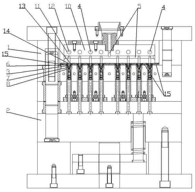
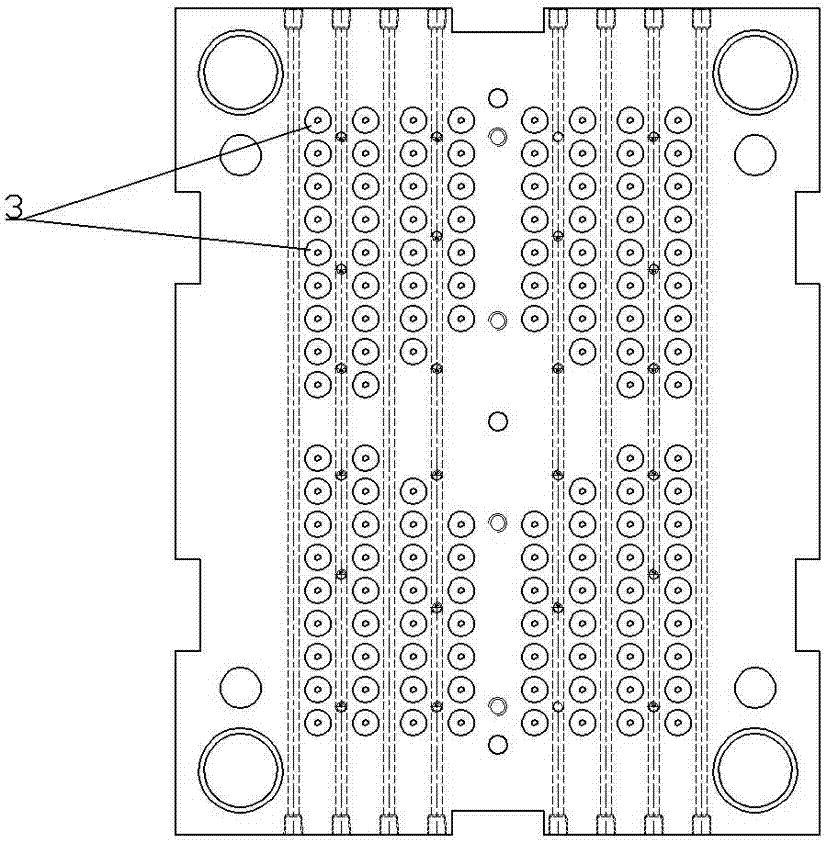
[0012] like figure 1 , figure 2 As shown, the deformation adjustment structure of the injection mold provided by the present invention includes a first template 1 and a second template 2, where the first template 1 and the second template 2 can be fixed molds or movable molds. In actual operation, the first The template 1 is a fixed mold, the first template 1 includes a pouring end 3 and a heating element 4, the pouring end 3 is in communication with the hot runner 5 on the first template 2, and the corresponding pouring end 3 on the first template 1 is also provided with The mold cavity, the pouring end 3 is covered with a heat insulation sleeve 6, the lower end of the heat insulation sleeve 6 has an opening 8 corresponding to the material outlet 7 of the pouring end 3, the first template 1 includes a metal template 10, and the heat flow The channel 5 is arranged in the metal formwork 10, and the metal formwork 10 and the pouring end 3 are separately arranged and fixed to e...


PUM


Abstract

The invention discloses a deformation adjusting structure of an injection mould. The deformation adjusting structure comprises a first template and a second template, wherein the first template comprises pouring ends and a heating element; the pouring ends are communicated with a hot runner on the first template; the first template comprises a metal template; the hot runner is arranged in the metal template; the metal template and the pouring ends are separated and mutually fixed through a detachable fastening device; the metal template and the pouring ends are in plane contact and form liquid sealing fit; a runner hole outlet at the lower end of the metal template is aligned with a pouring hole inlet at the upper end of each pouring end; and the pouring ends are mutually staggered in a distance. The pouring ends and the metal template are in detachable surface contact, the expansion and condensation of the pouring ends are not interfered by the metal template (or relatively low interference effect), and the distance is reserved between every two pouring ends, so that the damage of the mould is not caused by the expansion deformation of the pouring ends, and the runner hole outlet at the lower end of the metal template does not deviate from the pouring hole inlet at the upper end of each pouring end, thus conditions are provided for arranging the pouring ends, the working efficiency of the injection mould disclosed by the invention can be improved, and the production cost is lowered.

Description

technical field [0001] The invention relates to a deformation regulating structure of an injection mold in the injection mold industry. Background technique [0002] A traditional injection mold generally includes a first template and a second template. The first template is provided with an injection runner and a pouring end, and the second template is provided with a mold cavity. After the first template and the second template are connected, the plastic solution flows from the injection flow The pouring channel is injected into the pouring end, and then injected into the cavity of the first formwork from the pouring end. After cooling, the first formwork is separated from the second formwork. At this time, there are injection molding residues after cooling and solidification in the pouring channel of the first formwork. After the second template is separated to obtain the product, special personnel are required to take out the injection molding residue in the first templa...

Claims


Application Information

Patent Timeline
Patent Type & Authority Applications(China)
IPC IPC(8): B29C45/26
Inventor 黄联鑫周国明
Owner WENZHOU WENTAI PEN IND
Features
  • R&D
  • Intellectual Property
  • Life Sciences
  • Materials
  • Tech Scout
  • Unparalleled Data Quality
  • Higher Quality Content
  • 60% Fewer Hallucinations
Learn More