
Wheel disc false twisting spinning device

A roulette and false twisting technology, which is applied to spinning machines, continuous winding spinning machines, textiles and papermaking, etc., can solve the problems of difficult industrial application, difficult control, high investment and operation costs, etc.

Inactive Publication Date: 2013-05-08
陈子瑜
View PDF1 Cites 4 Cited by
  • Summary
  • Abstract
  • Description
  • Claims
  • Application Information

AI Technical Summary

Problems solved by technology

Not only the investment and operation cost is high, the operation is difficult, but also affects the production management and the overall benefit, so it is difficult to be suitable for industrial application

Method used


Image

  • Wheel disc false twisting spinning device
  • Wheel disc false twisting spinning device
  • Wheel disc false twisting spinning device

Examples


Embodiment Construction

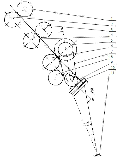
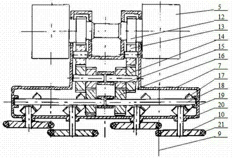
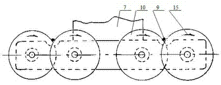
[0018] in figure 1 figure 2 image 3 The drafting part of the ring spinning frame is composed of top rear roller 1, bottom rear roller 2, top middle roller 3, bottom middle roller 4, top top roller 5, bottom front roller 6 and suction tube 8, etc. The device for twisting and false-twisting spinning is arranged between the front roller jaws composed of the front top roller 5 and the front bottom roller 6 and the yarn guide 11 at a position close to the front top roller 5. 10 and its transmission mechanism and the front top roller 5 are combined into a false twist component. The front top roller 5 is provided with a driving gear 12, and the driven gear 16 fixed on the auxiliary shaft 18 is driven through the intermediate gear 13, the double gears 14 and 15; the auxiliary shaft 18 is also fixed with two driving bevel gears 17, two The two driving bevel gears 17 respectively drive the corresponding two driven bevel gears 19, and the two driven bevel gears 19 drive the twisting whe...


PUM

PropertyMeasurementUnit
Outer diameteraaaaaaaaaa
Arc radiusaaaaaaaaaa
Helix angleaaaaaaaaaa

Abstract

The invention provides a false twisting spinning device. According to the false twisting spinning device, rotating wheel discs are used as false twisting components, each spindle position is provided with at least two twisting wheel discs, wherein the peripheries of the twisting wheel discs are overlapped in an eccentric and staggered mode, the two twisting wheel discs rotate in the same direction, slivers output from front rollers pass through a wedge groove formed by the two twisting wheel discs, two contact surfaces exist between the twisting wheel discs and the slivers, and the slivers are twisted by friction to revolve so that false twisting is achieved. The false twisting spinning device is characterized in that a false twisting spinning device is arranged at a position between a front roller jaw and a yarn guide hook, close to the front roller jaw; the false twisting spinning device and a front upper roller are integrally combined; a driving gear is arranged on the front upper roller, and drives a driven gear on an auxiliary shaft through a middle gear; and the auxiliary shaft is further provided with two driving bevel gears, the two driving bevel gears drive two corresponding driven bevel gears respectively, and the two driven bevel gears drive the twisting wheel discs on wheel disc shafts to rotate.

Description

Technical field [0001] The invention relates to the field of spinning equipment, and is a device for adding false twist in the spinning process of a ring spinning frame, in particular a false twist spinning device using a rotating wheel as a false twist element and a drafting roller as a driving power source. Background technique [0002] In the spinning process of ring spinning frame, the method of adding false twist to the spinning sliver has been used for decades to improve the spinning process conditions and / or yarn performance. In the disclosed technology, the false twist device They are all set in the spinning section between the front roller jaw and the yarn guide hook. The mechanical false twisting method can be roughly divided into mechanical center friction drive, wheel surface friction rolling, and double wheel disk based on the yarn false twisting movement mode. Or roulette group twisting, double-sided belt or belt group twisting, single-contact section tangent belt s...

Claims


Application Information

Patent Timeline
IPC IPC(8): D01H1/243D01H7/92
Inventor 陈子瑜
Owner 陈子瑜
Learn More